CRANKSHAFT POSITION SENSOR INSTALLATION

-
INSTALL CRANKSHAFT POSITION SENSOR
-
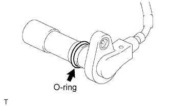
Apply a light coat of engine oil to the O-ring of the crankshaft position sensor.
-
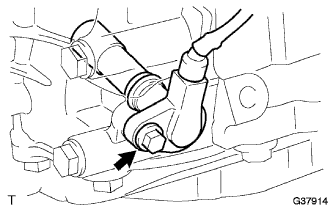
Install the crankshaft position sensor with the bolt.
- Torque:
- 8.5 N*m { 87 kgf*cm, 75 in.*lbf }
Note
Make sure that the O-ring is not cracked or jammed when installing.
-
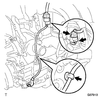
Connect the crankshaft position sensor connector and the 2 wire harness clamps.
-
-
INSTALL COMPRESSOR MOUNTING BRACKET NO.1 (w/ Air Conditioning)
-
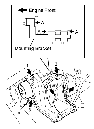
Temporarily install the mounting bracket with the 5 bolts.
Tech Tips
Make sure that the mounting bracket is in contact with the engine block at points A shown in the illustration.
-
Install the mounting bracket by tightening the 5 bolts in the order shown in the illustration.
- Torque:
- Bolt B
- 25 N*m { 255 kgf*cm, 18 ft.*lbf }
- Except bolt B
- 45 N*m { 459 kgf*cm, 33 ft.*lbf }
Note
In order to prevent misalignment, which causes belt rattle, tightening of the bolts must be performed in the order shown.
-
-
INSTALL COMPRESSOR AND MAGNETIC CLUTCH (w/ Air Conditioning)
-
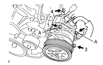
Temporarily install the bolt A to install the compressor.
-
Install the compressor completely by tightening the 4 bolts in the order shown in the illustration.
- Torque:
- 25 N*m { 255 kgf*cm, 18 ft.*lbf }
Note
In order to prevent misalignment, which causes belt rattle, tightening of the bolts must be performed in the order shown.
-
Connect the suction tube clamp with the bolt.
- Torque:
- 5.4 N*m { 55 kgf*cm, 48 in.*lbf }
-
Connect the compressor connector.
-
-
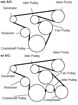
INSTALL FAN & GENERATOR V BELT (w/ Air Conditioning)
-
Install the drive belt to the pulleys except the drive belt tensioner pulley.
-
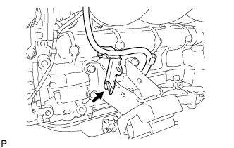
Use the hexagon-shaped part indicated by the arrow in the illustration to move the tensioner pulley downward and then install the drive belt to the tensioner pulley.
Note
-
The backside of the drive belt should face the tensioner pulley.
-
Check that the drive belt is properly set to each pulley.
-
-
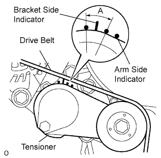
After a new belt has been installed, check that the tensioner indicator mark is within range A shown in the illustration.
-
-
INSTALL OIL LEVEL GAUGE GUIDE (w/ Air Conditioning)
-
Install the gauge guide with the bolt.
- Torque:
- 20 N*m { 204 kgf*cm, 15 ft.*lbf }
-
-
INSTALL ENGINE SERVICE HOLE SUB COVER SUB-ASSEMBLY (w/ Air Conditioning)
-
Install the engine service hole sub cover with the 5 bolts.
- Torque:
- 13 N*m { 133 kgf*cm, 10 ft.*lbf }
-
-
INSTALL FRONT DOOR SCUFF PLATE RH (w/ Air Conditioning)
-
INSTALL FRONT SEAT ASSEMBLY RH (for Hi-back Seat Type, w/ Air Conditioning)
-
Perform the same procedure as above on the opposite side. Click here
-
-
INSTALL FRONT SEAT ASSEMBLY RH (for Low-back Seat Type, w/ Air Conditioning)
-
Perform the same procedure as above on the opposite side. Click here
-
-
CONNECT CABLE TO NEGATIVE BATTERY TERMINAL
-
INSTALL ENGINE UNDER COVER NO.1 (w/ Engine Under Cover No.1 and Air Conditioning)
- Torque:
- 13 N*m { 133 kgf*cm, 10 ft.*lbf }
-
PERFORM INITIALIZATION