SFI SYSTEM (w/o Secondary Air Injection System) Injector Circuit
DESCRIPTION
The fuel injectors are located on the intake manifold. They inject fuel into the cylinders based on the signals from the ECM.
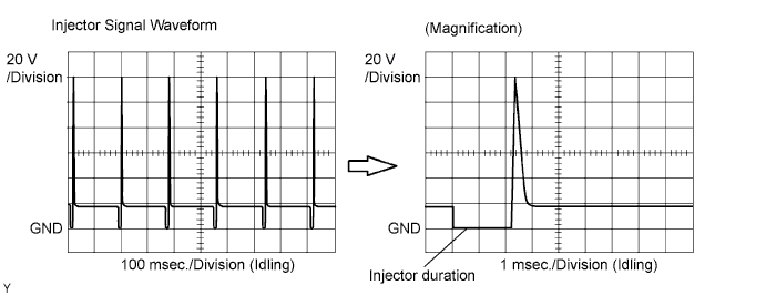
Reference: INSPECTION USING OSCILLOSCOPE
With the engine idling, check the waveform between terminals #1 to #4 and E01 of the ECM connectors.
Tech Tips
The correct waveform is as shown in the diagram below.
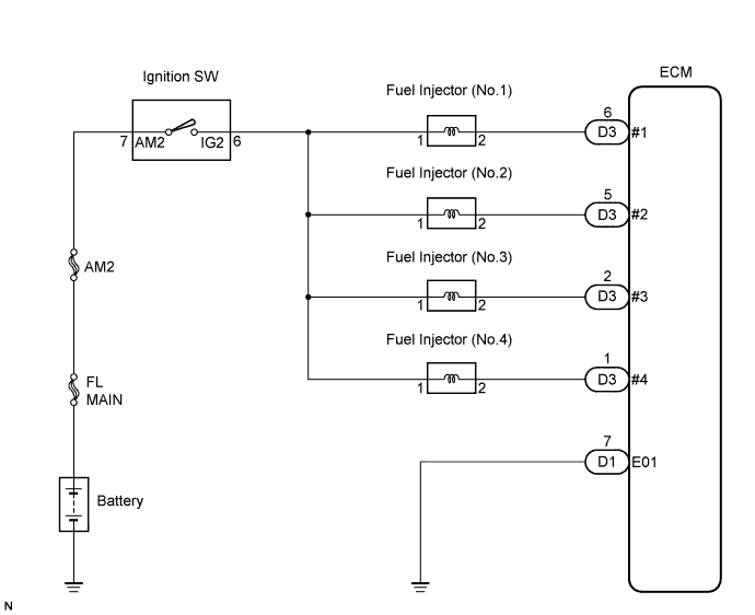
WIRING DIAGRAM
INSPECTION PROCEDURE
PROCEDURE
-
INSPECT ECM (#1, #2, #3 or #4 VOLTAGE)
-
Turn the ignition switch to the ON position.
-
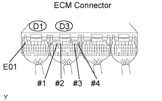
Measure the voltage between the terminals of the ECM connector.
Voltage Tester Connections Specified Conditions #1 (D3-6) - E01 (D1-7) 9 to 14 V #2 (D3-5) - E01 (D1-7) 9 to 14 V #3 (D3-2) - E01 (D1-7) 9 to 14 V #4 (D3-1) - E01 (D1-7) 9 to 14 V
OK 
CHECK HARNESS OR CONNECTOR (ECM GROUND) Click here
NG 
-
-
INSPECT FUEL INJECTOR ASSEMBLY
NG 
REPLACE FUEL INJECTOR ASSEMBLY
OK
-
CHECK HARNESS OR CONNECTOR (INJECTOR - ECM, INJECTOR - IGNITION SWITCH)
-
Check the harness and connectors between the injector and ECM.
-
Disconnect the injector connector(s).
-
Disconnect the D3 ECM connector.
-
Measure the resistance according to the value(s) in the table below.
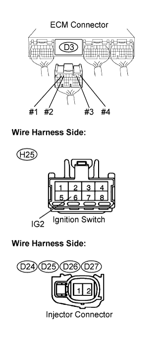
Resistance (Check for open) Tester Connection Specified Condition Injector (D24-2) - #1 (D3-6) Below 1 Ω Injector (D25-2) - #2 (D3-5) Below 1 Ω Injector (D26-2) - #3 (D3-2) Below 1 Ω Injector (D27-2) - #4 (D3-1) Below 1 Ω Resistance (Check for short) Tester Connection Specified Condition Injector (D24-2) or #1 (D3-6) - Body ground 10 kΩ or higher Injector (D25-2) or #2 (D3-5) - Body ground 10 kΩ or higher Injector (D26-2) or #3 (D3-2) - Body ground 10 kΩ or higher Injector (D27-2) or #4 (D3-1) - Body ground 10 kΩ or higher -
Reconnect the injector connector(s).
-
Reconnect the ECM connector.
-
-
Check the harness and connectors between the injector and ignition switch.
-
Disconnect the injector connector(s).
-
Disconnect the H25 ignition switch connector.
-
Measure the resistance according to the value(s) in the table below.
Resistance (Check for open) Tester Connection Specified Condition Injector (D24-1) - IG2 (H25-6) Below 1 Ω Injector (D25-1) - IG2 (H25-6) Below 1 Ω Injector (D26-1) - IG2 (H25-6) Below 1 Ω Injector (D27-1) - IG2 (H25-6) Below 1 Ω Resistance (Check for short) Tester Connection Specified Condition Injector (D24-1) or IG2 (H25-6) - Body ground 10 kΩ or higher Injector (D25-1) or IG2 (H25-6) - Body ground 10 kΩ or higher Injector (D26-1) or IG2 (H25-6) - Body ground 10 kΩ or higher Injector (D27-1) or IG2 (H25-6) - Body ground 10 kΩ or higher -
Reconnect the injector connector.
-
Reconnect the ignition switch connector.
-
NG
REPAIR OR REPLACE HARNESS OR CONNECTOR
OK 
CHECK ECM POWER SOURCE CIRCUIT
-
-
CHECK HARNESS OR CONNECTOR (ECM GROUND)
-
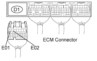
Disconnect the D1 ECM Connector.
-
Measure the resistance according to the value(s) in the table below.
Resistance Tester Connection Specified Condition E01 (D1-7) - Body ground Below 1 Ω E02 (D1-6) - Body ground Below 1 Ω -
Reconnect the ECM connector.
NG
REPAIR OR REPLACE HARNESS OR CONNECTOR
OK
-
-
INSPECT FUEL INJECTOR ASSEMBLY
NG
REPLACE FUEL INJECTOR ASSEMBLY
OK
PROCEED TO NEXT CIRCUIT INSPECTION SHOWN IN PROBLEM SYMPTOMS TABLE