SFI SYSTEM (w/o Secondary Air Injection System) Starter Signal Circuit
DESCRIPTION
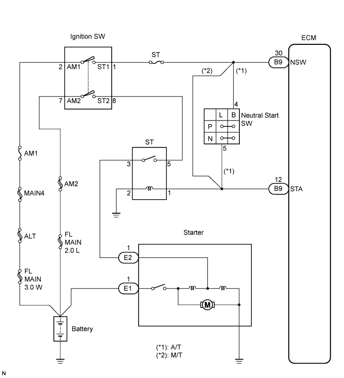
While the engine is being cranked, the positive battery voltage is applied to terminal STA of the ECM.
WIRING DIAGRAM
INSPECTION PROCEDURE
The following troubleshooting flowchart is based on the premise that the engine is cranked normally. If the engine will not crank, proceed to the problem symptoms table. Click here
PROCEDURE
-
READ VALUE USING INTELLIGENT TESTER (STA SIGNAL)
-
Connect an intelligent tester to the DLC3.
-
Turn the ignition switch to ON position and turn the tester on.
-
Select the following menu items: Powertrain / Engine and ECT / Data List / Starter Sig.
-
Check the value displayed on the tester when the ignition switch is turned to ON and START positions.
OK Ignition Switch Positions ON START Starter Sig OFF ON
OK 
PROCEED TO NEXT SUSPECTED AREA SHOWN IN PROBLEM SYMPTOMS TABLE
NG 
-
-
CHECK HARNESS AND CONNECTOR (ECM - ST RELAY)
NG
REPAIR OR REPLACE HARNESS OR CONNECTOR
OK
-
INSPECT STARTER RELAY
NG
REPLACE STARTER RELAY
OK 
REPLACE ECM