SFI SYSTEM (w/o Secondary Air Injection System), Diagnostic DTC:P0500

| DTC Code | DTC Name |
|---|---|
| P0500 | Vehicle Speed Sensor |
DESCRIPTION
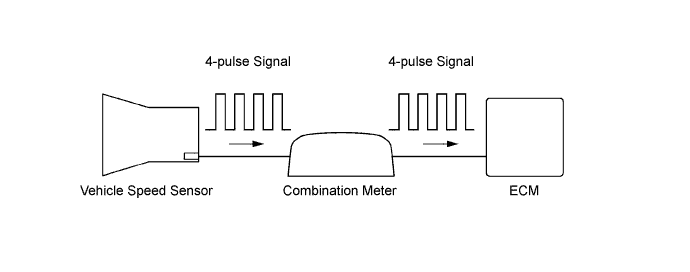
The vehicle speed sensor outputs a 4 pulse signal for every revolution of the rotor shaft, which is rotated by the transaxle output shaft via the driven gear. After this signal is converted into a more precise rectangular waveform by the waveform shaping circuit inside the combination meter, it is then transmitted to the ECM. The ECM determines the vehicle speed based on the frequency of the pulse signal.
| DTC No. | DTC Detection Condition | Trouble Area |
|---|---|---|
| P0500 | While vehicle is being driven, no vehicle speed sensor signal is sent to ECM (1 trip detection logic). |
|
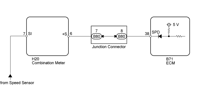
WIRING DIAGRAM
INSPECTION PROCEDURE
Tech Tips
Read freeze frame data using the intelligent tester. Freeze frame data records the engine condition when malfunctions are detected. When troubleshooting, freeze frame data can help determine if the vehicle was moving or stationary, if the engine was warmed up or not, if the air-fuel ratio was lean or rich, and other data from the time the malfunction occurred.
PROCEDURE
-
READ VALUE USING INTELLIGENT TESTER (VEHICLE SPEED)
-
Connect the intelligent tester to the DLC3.
-
Turn the ignition switch to ON.
-
Turn the intelligent tester on.
-
Enter the following menus: Powertrain / Engine and ECT / Data List / Vehicle Speed.
-
Drive the vehicle.
-
Read the value displayed on the intelligent tester.
OK Vehicle speeds displayed on intelligent tester and speedometer display are equal.
NG 
CHECK COMBINATION METER SYSTEM Click here
OK 
CHECK FOR INTERMITTENT PROBLEMS Click here
-
-
CHECK COMBINATION METER SYSTEM
-
Inspect the circuits that send vehicle speed signals to this system in the meter system Click here.
-
During inspection for the meter section, if there is an instruction that indicates to go back to inspections for each system, proceed to the next step.
NEXT 
-
-
CHECK HARNESS AND CONNECTOR (ECM - COMBINATION METER)
-
Disconnect the ECM connector.
-
Disconnect the combination meter connector.
-
Measure the resistance according to the value(s) in the table below.
Standard Resistance Tester Connection Condition Specified Condition H20-6 (+S) - B71-38 (SPD) Always Below 1 Ω
NG
CHECK HARNESS AND CONNECTOR (ECM - JUNCTION CONNECTOR) Click here
OK
REPLACE ECM Click here
-
-
CHECK HARNESS AND CONNECTOR (ECM - JUNCTION CONNECTOR)
-
Disconnect the ECM connector.
-
Disconnect the junction connector.
-
Measure the resistance according to the value(s) in the table below.
Standard Resistance Tester Connection Condition Specified Condition B80-8 - B71-38 (SPD) Always Below 1 Ω
NG 
REPAIR OR REPLACE HARNESS OR CONNECTOR (ECM - JUNCTION CONNECTOR)
OK
REPAIR OR REPLACE HARNESS OR CONNECTOR (JUNCTION CONNECTOR IS DEFECTIVE)
-