SFI SYSTEM (w/o Secondary Air Injection System), Diagnostic DTC:P0327/52, P0328/52

| DTC Code | DTC Name |
|---|---|
| P0327/52 | Knock Sensor 1 Circuit Low Input (Bank 1 or Single Sensor) |
| P0328/52 | Knock Sensor 1 Circuit High Input (Bank 1 or Single Sensor) |
DESCRIPTION
A flat type knock sensor (non-resonant type) has a structure that can detect vibrations over a wide band of frequencies: between approximately 6 kHz and 15 kHz.
Knock sensors are fitted onto the engine block to detect engine knocking.
The knock sensor contains a piezoelectric element which generates a voltage when it becomes deformed.
The voltage is generated when the engine block vibrates due to knocking. Any occurrence of engine knocking can be suppressed by delaying the ignition timing.
| DTC No. | DTC Detection Conditions | Trouble Areas |
|---|---|---|
| P0327/52 | Output voltage of knock sensor 0.5 V or less (1 trip detection logic) |
|
| P0328/52 | Output voltage of knock sensor 4.5 V or more (1 trip detection logic) |
|
Tech Tips
When any of DTCs P0327 and P0328 are set, the ECM enters fail-safe mode. During fail-safe mode, the ignition timing is delayed to its maximum retardation. Fail-safe mode continues until the ignition switch is turned to OFF.
The correct waveform is shown.
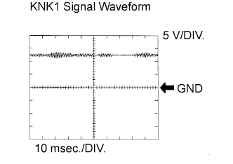
| Items | Contents |
| Terminals | KNK1 - EKNK |
| Equipment Settings | 0.01 to 10 V/Division, 0.01 to 10 msec./Division |
| Conditions | Keep engine speed at 4,000 rpm with warm engine |
MONITOR DESCRIPTION
If the output voltage transmitted by the knock sensor remains low or high for more than 1 seconds, the ECM interprets this as a malfunction in the sensor circuit, and sets a DTC.
The monitor for DTCs P0327 and P0328 begins to run when 5 seconds have elapsed since the engine was started.
If the malfunction is not repaired successfully, any of DTC P0327 or P0328 is set 5 seconds after the engine is next started.
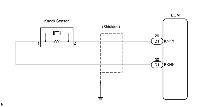
WIRING DIAGRAM
INSPECTION PROCEDURE
Tech Tips
Read freeze frame data using an intelligent tester. The ECM records vehicle and driving condition information as freeze frame data the moment a DTC is stored. When troubleshooting, freeze frame data can be helpful in determining whether the vehicle was running or stopped, whether the engine was warmed up or not, whether the air-fuel ratio was lean or rich, as well as other data recorded at the time of a malfunction.
PROCEDURE
-
CHECK HARNESS AND CONNECTOR (ECM - KNOCK SENSOR)
-
Disconnect the D1 ECM connector.
-
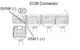
Measure the resistance between the terminals of the ECM connector.
Resistance Tester Connections Specified Conditions KNK1 (D1-29) - EKNK (D1-30) 120 to 280 kΩ at 20°C (68°F) -
Reconnect the ECM connector.
NG 
INSPECT KNOCK CONTROL SENSOR Click here
OK 
-
-
INSPECT ECM (KNK1 VOLTAGE)
-
Disconnect the D1 ECM connector.
-
Turn the ignition switch to the ON position.
-
Measure the voltage between the ECM terminals.
Voltage Tester Connections Specified Conditions KNK1 (D1-29) - EKNK (D1-30) 4.5 to 5.5 V -
Reconnect the ECM connector.
Note
Faults may be intermittent. Check the wire harness and connector carefully and retest.
NG 
REPLACE ECM
OK 
CHECK FOR INTERMITTENT PROBLEMS
-
-
INSPECT KNOCK CONTROL SENSOR
-
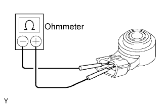
Remove the knock sensor.
-
Measure the resistance between the terminals.
Resistance Tester Connections Specified Conditions KNK1 (g1-2) - EKNK (g1-1) 120 to 280 kΩ at 20°C (68°F) -
Reinstall the knock sensor.
NG
REPLACE KNOCK CONTROL SENSOR
OK
REPAIR OR REPLACE HARNESS OR CONNECTOR
-