SFI SYSTEM (w/o Secondary Air Injection System), Diagnostic DTC:P0135

| DTC Code | DTC Name |
|---|---|
| P0135 | Oxygen (A/F) Sensor Heater Circuit (Bank 1 Sensor 1) |
DESCRIPTION
Refer to DTC P0130. Click here
| DTC No. | DTC Detecting Condition | Trouble Area |
|---|---|---|
| P0135 | When heater operates, heater current exceeds 2 A (2 trip detection logic) |
|
| Heater current of 0.2 A or less when heater operates (2 trip detection logic) |
WIRING DIAGRAM
Refer to DTC P0130 Click here.
INSPECTION PROCEDURE
Tech Tips
Read freeze frame data using the intelligent tester. The ECM records vehicle and driving condition information as freeze frame data the moment a DTC is stored. When troubleshooting, freeze frame data can be helpful in determining whether the vehicle was running or stopped, whether the engine was warmed up or not, whether the air-fuel ratio was lean or rich, as well as other data recorded at the time of a malfunction.
PROCEDURE
-
INSPECT HEATED OXYGEN SENSOR
-
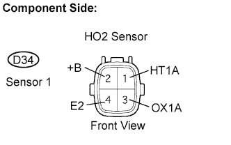
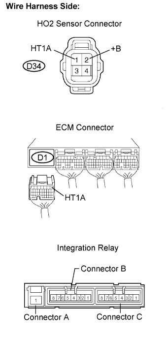
Disconnect the D34 Heated Oxygen (HO2) sensor connector.
-
Measure the resistance between the terminals of the HO2 sensor connector.
Resistance Tester Connections Specified Conditions HT1A (1) - +B (2) 11 to 16 Ω at 20°C (68°F) HT1A (1) - E2 (4) 10 kΩ or higher -
Reconnect the HO2 sensor connector.
NG 
REPLACE HEATED OXYGEN SENSOR
OK 
-
-
INSPECT ECM (HT1B VOLTAGE)
-
Turn the ignition switch to the ON position.
-
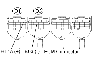
Measure the voltage between the terminals of the ECM connectors.
Voltage Tester Connections Specified Conditions HT1A (D1-1) - E03 (D3-4) 9 to 14 V
NG 
INSPECT ECM POWER SOURCE CIRCUIT Click here
OK
-
-
CHECK HARNESS AND CONNECTOR (HO2 SENSOR - ECM, HO2 - INTEGRATION RELAY)
-
Check the harness and connectors between the ECM and HO2 sensor.
-
Disconnect the D34 or HO2 sensor connector.
-
Disconnect the D1 ECM connector.
-
Measure the resistance.
Resistance (Check for open) Tester Connections Specified Conditions HT1A (D34-1) - HT1A (D1-1) Below 1 Ω Resistance (Check for short) Tester Connections Specified Conditions HT1A (D34-1) or HT1A (D1-1) - Body ground 10 kΩ or higher -
Reconnect the HO2 sensor connector.
-
Reconnect the ECM connector.
-
-
Check the harness and connector between the HO2 sensor and integration relay (MAIN relay).
-
Disconnect the D35 HO2 sensor connector.
-
Remove the integration relay from the engine room No.1.
-
Measure the resistance.
Resistance (Check for open) Tester Connections Specified Conditions +B (D34-2) - Integration relay (B4) Below 1 Ω Resistance (Check for short) Tester Connections Specified conditions +B (D34-2) or Integration relay (B4)
- Body ground
10 kΩ or higher -
Reconnect the HO2 sensor connector.
-
Reinstall the integration relay (MAIN relay).
-
NG
REPAIR OR REPLACE HARNESS OR CONNECTOR
OK
-
-
INSPECT ECM POWER SOURCE CIRCUIT
NG
REPAIR OR REPLACE ECM POWER SOURCE CIRCUIT
OK 
REPLACE ECM