SFI SYSTEM (w/o Secondary Air Injection System), Diagnostic DTC:P0130

| DTC Code | DTC Name |
|---|---|
| P0130 | Oxygen (A/F) Sensor Circuit (Bank 1 Sensor 1) |
DESCRIPTION
To obtain a high purification rate for the CO, HC and NOx components of the exhaust gas, a three-way catalytic converter is used, but for the most efficient use of the three-way catalytic converter, the air-fuel ratio must be precisely controlled so that it is always close to the stoichiometric air-fuel ratio.
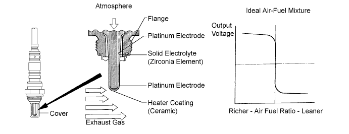
The heated oxygen sensor has the characteristic where by its output voltage changes suddenly in the vicinity of the stoichiometric air-fuel ratio. This is used to detect the oxygen concentration in the exhaust gas and provide the ECM with feedback to control the air-fuel ratio.
When the air-fuel ratio becomes LEAN, the oxygen concentration in the exhaust gas increases. And the heated oxygen sensor informs the ECM of the LEAN condition (small electromotive force: <0.45 V).
When the air-fuel ratio is RICHER than the stoichiometric air-fuel ratio, the oxygen concentration in the exhaust gas is reduced. And the heated oxygen sensor informs the ECM of the RICH condition (large electromotive force: >0.45 V). The ECM judges by the electromotive force from the heated oxygen sensor whether the air-fuel ratio is RICH or LEAN and controls the injection time accordingly. However, if the malfunction of the heated oxygen sensor causes an output of abnormal electromotive force, the ECM becomes unable to perform the accurate air-fuel ratio control.
The heated oxygen sensor is included a heater which heats the zirconia element. The heater is controlled by the ECM. When the intake air volume is low (the temperature of the exhaust gas is low), current flows to the heater in order to heat the sensor for the accurate oxygen concentration detection.
| DTC No. | DTC Detecting Condition | Trouble Area |
|---|---|---|
| P0130 |
|
|
Tech Tips
After confirming DTC P0130, use the intelligent tester to confirm the output voltage of the heated oxygen sensor from the "Powertrain / Engine and ECT / Data List". If voltage output of the heated oxygen sensor is less than 0.1 V, the heated oxygen sensor circuit may be open or short.
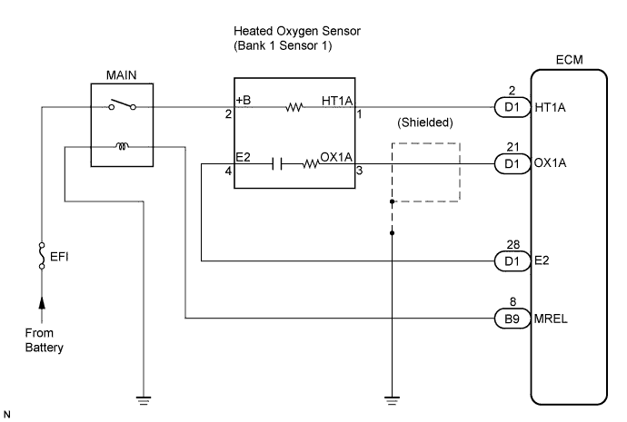
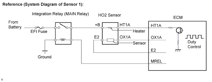
WIRING DIAGRAM
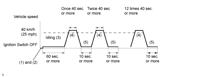
CONFIRMATION DRIVING PATTERN
(1) Connect the intelligent tester to the DLC3.
(2) Switch the intelligent tester from the normal mode to the check mode.
(3) Start the engine and let the engine idle for 60 seconds or more.
(4) Drive the vehicle at 40 km/h (25 mph) or more for 40 seconds or more.
(5) Let the engine idle for 10 seconds or more.
(6) Perform steps (4) and (5) 12 times.
Tech Tips
If a malfunction exists, the MIL will light up during step (6).
Note
If the conditions in this test are not strictly followed, detection of the malfunction will not be possible. If you do have an intelligent tester, turn the ignition switch OFF after performing steps from (3) to (6), then perform steps from (3) to (6) again.
INSPECTION PROCEDURE
Tech Tips
-
Read freeze frame data using the intelligent tester. The ECM records vehicle and driving condition information as freeze frame data the moment a DTC is stored. When troubleshooting, freeze frame data can be helpful in determining whether the vehicle was running or stopped, whether the engine was warmed up or not, whether the air-fuel ratio was lean or rich, as well as other data recorded at the time of a malfunction.
-
If different DTCs that are related to different systems are output simultaneously while terminal E2 is used as a ground terminal, terminal E2 may be open.
PROCEDURE
-
CHECK OTHER DTC OUTPUT (BESIDES P0130)
-
Connect the intelligent tester to the DLC3.
-
Turn the ignition switch to the ON position and turn the tester ON.
-
Select the following menu items: Powertrain / Engine and ECT / DTC.
-
Read DTCs.
Result Display (DTC Output) Proceed To P0130 A Other DTCs are output besides P0130 B Tech Tips
If any other codes besides P0130 is output, perform the troubleshooting on that DTC first.
B 
GO TO DTC CHART
A 
-
-
READ VALUE USING INTELLIGENT TESTER (OUTPUT VOLTAGE OF HEATED OXYGEN SENSOR)
-
Warm up the engine to the normal operating temperature above 75°C (169°F).
-
Connect the intelligent tester to the DLC3.
-
Turn the ignition switch to the ON position and turn the tester ON.
-
Select the following menu items: Powertrain / Engine and ECT / Data List / O2S B1S2.
-
Allow the engine to idle.
-
Read the Heated Oxygen (HO2) sensor output voltage when the engine is suddenly raced.
Standard Heated oxygen sensor outputs a RICH signal (0.45 V or more) at least once Tech Tips
Perform a quick racing to 4,000 rpm 3 times by using the accelerator pedal.
OK 
PERFORM CONFIRMATION DRIVING PATTERN Click here
NG
-
-
CHECK PCV HOSE
NG
REPAIR OR REPLACE PCV HOSE
OK
-
INSPECT HEATED OXYGEN SENSOR
NG
REPLACE HEATED OXYGEN SENSOR
OK
-
CHECK HARNESS AND CONNECTOR (HEATED OXYGEN SENSOR - ECM)
-
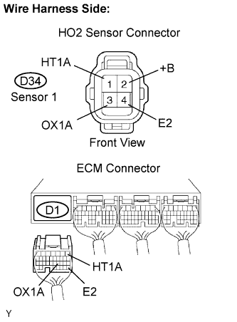
Disconnect the D34 HO2 sensor connector.
-
Turn the ignition switch to the ON position.
-
Measure the voltage between the +B terminal of the HO2 sensor connector and body ground.
Voltage Tester Connections Specified Conditions +B (D34-2) - Body ground 9 to 14 V -
Turn the ignition switch to OFF.
-
Disconnect the D1 ECM connector.
-
Measure the resistance.
Resistance (Check for open) Tester Connections Specified Conditions HT1A (D34-1) - HT1A (D1-1) Below 1 Ω OX1A (D34-3) - OX1A (D1-21) Below 1 Ω E2 (D34-4) - E2 (D1-28) Below 1 Ω Resistance (Check for short) Tester Connections Specified Conditions HT1A (D34-1) or HT1A (D1-1) - Body ground 10 kΩ or higher OX1A (D34-3) or OX1A (D1-21) - Body ground 10 kΩ or higher E2 (D34-4) or E2 (D1-28) - Body ground 10 kΩ or higher -
Reconnect the HO2 sensor connector.
-
Reconnect the ECM connector.
NG
REPAIR OR REPLACE HARNESS OR CONNECTOR
OK
-
-
CHECK WHETHER MISFIRE IS OCCURRED OR NOT BY MONITORING DTC AND DATA LIST
NG
CHECK FOR SPARK AND IGNITION
OK
-
CHECK AIR INDUCTION SYSTEM
NG
REPAIR OR REPLACE AIR INDUCTION SYSTEM
OK
-
CHECK FUEL PRESSURE
NG
REPAIR OR REPLACE FUEL SYSTEM
OK
-
INSPECT FUEL INJECTOR ASSEMBLY (INJECTION VOLUME)
NG
REPLACE FUEL INJECTION ASSEMBLY
OK
-
CHECK FOR EXHAUST GAS LEAKS
NG
REPAIR OR REPLACE EXHAUST GAS LEAKAGE POINT
OK 
REPLACE HEATED OXYGEN SENSOR
-
PERFORM CONFIRMATION DRIVING PATTERN
-
Clear the DTC.
-
Warm up the heated oxygen sensor by performing a driving test to check the system.
Tech Tips
Refer to CONFIRMATION DRIVING PATTERN.
NEXT
-
-
READ OUTPUT DTC (DTC P0130 IS OUTPUT AGAIN)
-
Connect the intelligent tester to the DLC3.
-
Turn the ignition switch to the ON position and turn the tester ON.
-
Select the following menu items: Powertrain / Engine and ECT / DTC.
-
Read DTCs.
Result Display (DTC Output) Proceed To P0130 A Other DTCs are output besides P0130 B
A
REPLACE HEATED OXYGEN SENSOR
B
-
-
CONFIRM IF VEHICLE RAN OUT OF FUEL IN PAST
-
Confirm if the vehicle ran out of fuel or not in the past.
Tech Tips
There is no problem, if DTC P0130 is not output after the CONFIRMATION DRIVING PATTERN. This means that the ECM records DTC P0130 because of the running out of fuel in the past.
NO
CHECK FOR INTERMITTENT PROBLEMS
YES
DTC IS CAUSED BY RUNNING OUT OF FUEL
-