SFI SYSTEM (w/o Secondary Air Injection System), Diagnostic DTC:P0016/18

| DTC Code | DTC Name |
|---|---|
| P0016/18 | Crankshaft Position - Camshaft Position Correlation (Bank 1 Sensor A) |
DESCRIPTION
Refer to DTC P0335/13 Click here.
| DTC No. | DTC Detection Conditions | Trouble Areas |
|---|---|---|
| P0016/18 | Deviations in crankshaft and camshaft position sensor signals (2 trip detection logic) |
|
MONITOR DESCRIPTION
The ECM optimizes the valve timing by using the VVT (Variable Valve Timing) system to control the intake camshaft. The VVT system includes the ECM, the Oil Control Valve (OCV) and the VVT controller.
The ECM sends a target duty-cycle control signal to the OCV. This control signal regulates the oil pressure supplied to the VVT controller. The VVT controller can advance or retard the intake camshaft. The ECM calibrates the intake valve timing by setting the intake camshaft to the most retarded angle while the engine is idling. The ECM closes the OCV to retard the cam. The ECM stores this value as the VVT learning value. When the difference between the target and actual intake valve timings is 5°CA (Crankshaft Angle) or less, the ECM stores it.
If the VVT learning value matches the following conditions, the ECM determines the existence of a malfunction in the VVT system, and sets the DTC.
-
VVT learning value: Less than 31°CA, or more than 53°CA.
-
Above condition continues for 18 seconds or more.
This DTC indicates that the intake camshaft has been installed toward the crankshaft at an incorrect angle, caused by factors such as the timing chain having jumped a tooth.
This monitor begins to run after the engine has idled for 5 minutes.
WIRING DIAGRAM
Refer to DTC P0335/13 Click here.
INSPECTION PROCEDURE
Tech Tips
Read freeze frame data using an intelligent tester. The ECM records vehicle and driving condition information as freeze frame data the moment a DTC is stored. When troubleshooting, freeze frame data can be helpful in determining whether the vehicle was running or stopped, whether the engine was warmed up or not, whether the air-fuel ratio was lean or rich, as well as other data recorded at the time of a malfunction.
PROCEDURE
-
CHECK VALVE TIMING (CHECK FOR LOOSE AND JUMPED TEETH ON TIMING CHAIN)
-
Remove the cylinder head cover Click here.
-
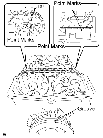
Turn the crankshaft pulley, and align its groove with the timing mark "0" on the timing chain cover.
-
Check that the point marks on the camshaft timing gears are as shown in the illustration.
If not, turn the crankshaft 1 revolution (360°) and align the marks as shown in the illustration.
OK Point marks on the camshaft timing gears are aligned as shown in illustration. -
Reinstall the cylinder head cover.
NG 
ADJUST VALVE TIMING
OK 
-
-
REPLACE ECM
NEXT
-
CHECK DTC
-
Connect an intelligent tester to the DLC3.
-
Turn the ignition switch to the ON position.
-
Turn the tester ON.
-
Clear DTCs Click here.
-
Switch the ECM from normal mode to check mode using the tester Click here.
-
Start the engine and warm it up.
-
Allow the engine to idle for 1 minute or more, and then drive the vehicle for 1 minute or more.
-
Confirm that no DTC is set using the tester.
NEXT 
END
-