SFI SYSTEM (w/o Secondary Air Injection System), Diagnostic DTC:P0010/39

| DTC Code | DTC Name |
|---|---|
| P0010/39 | Camshaft Position "A" Actuator Circuit (Bank 1) |
DESCRIPTION
Tech Tips
This DTC relates to the Oil Control Valve (OCV).
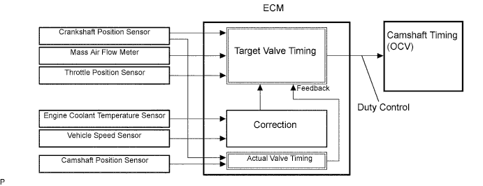
The Variable Valve Timing (VVT) system includes the ECM, OCV and VVT controller. The ECM sends a target duty-cycle control signal to the OCV. This control signal regulates the oil pressure supplied to the VVT controller. Camshaft timing control is performed according to engine operating conditions such as the intake air volume, throttle valve position and engine coolant temperature.
The ECM controls the OCV, based on the signals transmitted by several sensors. The VVT controller regulates the intake camshaft angle using oil pressure through the OCV. As a result, the relative positions of the camshaft and crankshaft are optimized, the engine torque and fuel economy improve, and the exhaust emissions decrease under overall driving conditions. The ECM detects the actual intake valve timing using signals from the camshaft and crankshaft position sensors, and performs feedback control. This is how the target intake valve timing is verified by the ECM.
| DTC No. | DTC Detection Conditions | Trouble Areas |
|---|---|---|
| P0010/39 | Open or short in OCV circuit (1 trip detection logic) |
|
MONITOR DESCRIPTION
The ECM optimizes the valve timing using the VVT system to control the intake camshaft. The VVT system includes the ECM, the OCV and the VVT controller. The ECM sends a target duty-cycle control signal to the OCV. This control signal regulates the oil pressure supplied to the VVT controller. The VVT controller can advance or retard the intake camshaft.
After the ECM sends the target duty-cycle signal to the OCV, the ECM monitors the OCV current to establish an actual duty-cycle. The ECM determines the existence of a malfunction and sets the DTC when the actual duty-cycle ratio varies from the target duty-cycle ratio.
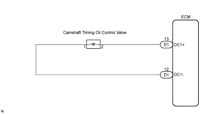
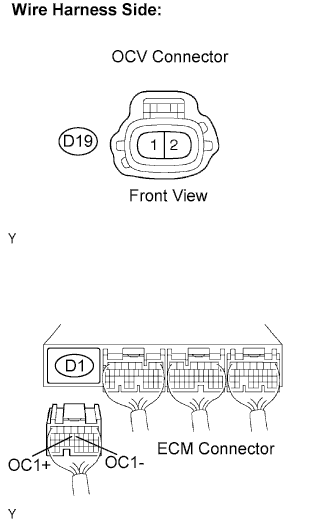
WIRING DIAGRAM
INSPECTION PROCEDURE
Tech Tips
Read freeze frame data using an intelligent tester. The ECM records vehicle and driving condition information as freeze frame data the moment a DTC is stored. When troubleshooting, freeze frame data can be helpful in determining whether the vehicle was running or stopped, whether the engine was warmed up or not, whether the air-fuel ratio was lean or rich, as well as other data recorded at the time of a malfunction.
PROCEDURE
-
PERFORM ACTIVE TEST USING INTELLIGENT TESTER (OPERATE OCV)
-
Start the engine and warm it up.
-
Turn the ignition switch to OFF.
-
Connect the intelligent tester to the DLC3.
-
Turn the ignition switch to the ON position and turn the intelligent tester ON.
-
Select the following menu items: Powertrain / Engine and ECT / Active Test / Active the VVT System (Bank 1).
-
Check the engine speed when operating the OCV using the intelligent tester.
OK Tester Operation Specified Condition OCV is OFF Normal engine speed OCV is ON Rough idling or engine stalling
OK 
CHECK FOR INTERMITTENT PROBLEMS
NG 
-
-
INSPECT CAMSHAFT TIMING OIL CONTROL VALVE ASSEMBLY
-
Disconnect the D19 OCV connector.
-
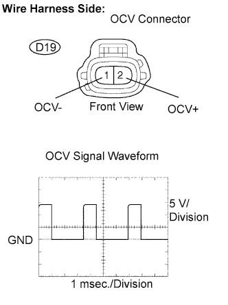
While idling, check the waveform between the terminals of the OCV connector using an oscilloscope.
Standard Tester Connections Specified Conditions OCV+ (D19-2) - OCV- (D19-1) Correct waveform shown in the illustration appears -
Reconnect the OCV connector.
NG
REPLACE CAMSHAFT TIMING OIL CONTROL VALVE ASSEMBLY
OK
-
-
INSPECT ECM (OCV SIGNAL)
-
Inspect the ECM using an oscilloscope.
-
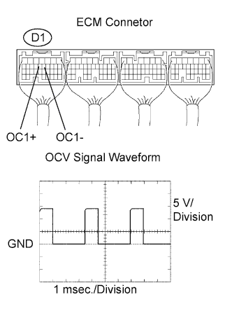
While idling, check the waveform between the terminals of the D1 ECM connector.
Standard Tester Connections Specified Conditions OC1+ (D1-13) - OC1- (D1-12) Correct waveform shown in the illustration appears
NG
REPLACE ECM
OK
-
-
CHECK HARNESS AND CONNECTOR (OCV - ECM)
-
Disconnect the D19 OCV connector.
-
Disconnect the D1 ECM connector.
-
Measure the resistance according to the value(s) in the table below.
Resistance (Check for open) Tester connection Specified condition OCV (D19-2) - OC1+ (D1-13) Below 1 Ω OCV (D19-1) - OC1- (D1-12) Below 1 Ω Resistance (Check for short) Tester connection Specified condition OCV (D19-2) or OC1+ (D1-13) - Body ground 10 kΩ or higher OCV (D19-1) - OC1- (D1-12) - Body ground 10 kΩ or higher -
Reconnect the OCV connector.
-
Reconnect the ECM connector.
NG
REPAIR OR REPLACE HARNESS OR CONNECTOR
OK 
CHECK FOR INTERMITTENT PROBLEMS
-