SFI SYSTEM (w/ Secondary Air Injection System) Fuel Pump Control Circuit
DESCRIPTION
When the engine is cranked, a current flows from terminal ST2 of the ignition switch into the STA (starter) relay coil and a current also flows into terminal STA of the ECM (STA signal).
When the STA and NE signals are received by the ECM, Tr (power transistor) is switched on, allowing a current to flow into the circuit opening relay coil. The circuit opening relay switches on, power is supplied to the fuel pump and the fuel pump operates.
While the NE signal is being generated (engine running), the ECM keeps Tr ON, therefore keeping the circuit opening relay ON, so that the fuel pump continues to operate.
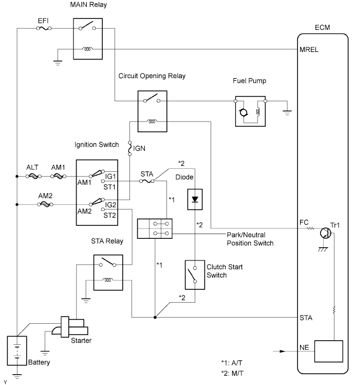
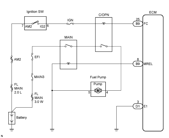
WIRING DIAGRAM
INSPECTION PROCEDURE
PROCEDURE
-
PERFORM ACTIVE TEST USING INTELLIGENT TESTER
-
Connect an intelligent tester to the DLC3.
-
Turn the ignition switch to the ON position and turn the tester ON.
-
Select the following menu items: Powertrain / Engine and ECT / Active Test / Fuel Pump / Spd.
-
Check whether the relay operating sounds can be heard while operating the relay using the tester.
OK Relay operating sounds can be heard from relay.
OK 
INSPECT FUEL PUMP ASSEMBLY Click here
NG 
-
-
INSPECT ECM POWER SOURCE CIRCUIT
NG 
REPAIR OR REPLACE ECM POWER SOURCE CIRCUIT
OK
-
INSPECT INTEGRATION NO.1 RELAY (CIRCUIT OPENING RELAY)
-
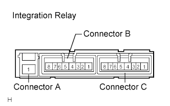
Remove the integration relay from the engine room R/B No.1.
-
Check the integration relay (CIRCUIT OPENING RELAY).
Resistance Tester Connection Specified Conditions B4 - B8 10 kΩ or higher B4 - B8 Below 1 Ω
(When battery voltage applied to terminals B6 and B7)
-
Reinstall the integration relay.
NG
REPLACE INTEGRATION NO.1 RELAY
OK
-
-
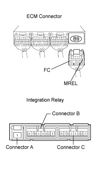
INSPECT ECM (FC VOLTAGE)
-
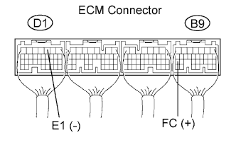
Turn the ignition switch to the ON position.
-
Measure the voltage between the terminals of the ECM connectors.
Voltage Tester Connections Specified Conditions FC (B9-25) - E1 (D1-3) 9 to 14 V
OK
REPLACE ECM
NG
-
-
CHECK HARNESS AND CONNECTOR (ECM - INTEGRATION RELAY)
-
Remove the integration relay from the engine room R/B No.1.
-
Disconnect the B9 ECM connector.
-
Measure the resistance according to the value(s) in the table below.
Resistance (Check for open) Tester Connection Specified Condition Integration relay (B2) - MREL (B9-8) Below 1 Ω Integration relay (B7) - FC (B9-25) Below 1 Ω Resistance (Check for short) Tester Connection Specified Condition Integration relay (B2) or MREL (B9-8)
- Body ground
10 kΩ or higher Integration relay (B7) or FC (B9-25)
- Body ground
10 kΩ or higher -
Reinstall the ECM connector.
-
Reinstall the integration relay.
NG
REPAIR OR REPLACE HARNESS OR CONNECTOR
OK 
REPLACE ECM
-
-
INSPECT FUEL PUMP ASSEMBLY
NG
REPLACE FUEL PUMP ASSEMBLY
OK
-
CHECK HARNESS AND CONNECTOR (INTEGRATION RELAY - FUEL PUMP, FUEL PUMP - BODY GROUND)
-
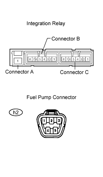
Remove the integration relay from the engine room R/B No.1.
-
Disconnect the fuel pump connector.
-
Measure the resistance according to the value(s) in the table below.
Resistance (Check for open) Tester Connection Specified Condition Integration relay (B8) - Fuel pump (4) Below 1 Ω Fuel pump (5) - Body ground Below 1 Ω Resistance (Check for short) Tester Connection Specified Condition Integration relay (B8) or Fuel pump (4)
- Body ground
10 kΩ or higher -
Reinstall the integration relay.
-
Reconnect the fuel pump connector.
NG
REPAIR OR REPLACE HARNESS OR CONNECTOR
OK
CHECK AND REPLACE INTEGRATION NO.1 RELAY (EFI RELAY AND CIRCUIT OPENING RELAY)
-