SFI SYSTEM (w/ Secondary Air Injection System), Diagnostic DTC:P2431, P2432, P2433

| DTC Code | DTC Name |
|---|---|
| P2431 | Secondary Air Injection System Air Flow / Pressure Sensor Circuit Range / Performance Bank1 |
| P2432 | Secondary Air Injection System Air Flow / Pressure Sensor Circuit Low Bank1 |
| P2433 | Secondary Air Injection System Air Flow / Pressure Sensor Circuit High Bank1 |
DESCRIPTION
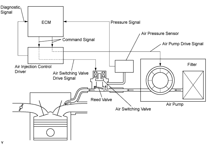
The secondary air injection system consists of an air pump, the air switching valve, an air pressure sensor, the air injection control driver and the ECM. For a short time after cold engine starts, the air injection system pumps secondary air to the exhaust port of the cylinder head to purify the exhaust emissions. The secondary air is supplied by the air pump and is pumped to the exhaust port through the air switching valve.
The air injection control driver drives the air switching valve and the air pump according to command signals transmitted by the ECM. The air pressure sensor detects the pressure in the secondary air passage when the air injection system is ON and OFF, and transmits pressure signal to the ECM.
The air injection control driver is not only equipped to drive the pump and valve, but also with a diagnosis function to detect malfunctions in the air injection system circuit.
Tech Tips
As a large current is required to drive the air pump and air switching valve, an air injection control driver is included in this system.
| DTC No. | DTC Detection Condition | Trouble Area |
|---|---|---|
| P2431 | Air pressure sensor indicates less than 45.63 kPa (342 mmHg), or more than 135 kPa (1013 mmHg) (2 trip detection logic) |
|
| P2432 | While engine running, voltage output of air pressure sensor remains below 0.5 V (1 trip detection logic) |
|
| P2433 | While engine running, voltage output of air pressure sensor remains above 4.5 V (1 trip detection logic) |
|
MONITOR DESCRIPTION
The ECM monitors the pressure in the secondary air passage using the air pressure sensor located on the cylinder head cover.
If there is a defect in the sensor or the sensor circuit, the voltage level deviates from the normal operating range, the ECM interprets this deviation as a malfunction in the air pressure sensor or circuit and sets a DTC.
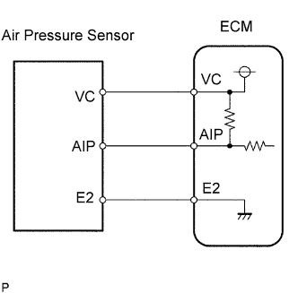
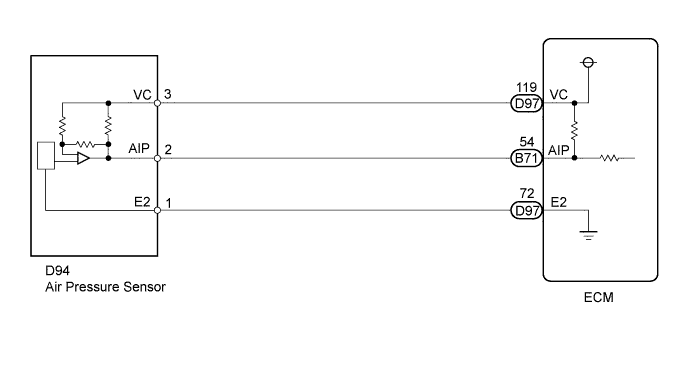
WIRING DIAGRAM
INSPECTION PROCEDURE
Tech Tips
Read freeze frame data using the intelligent tester. Freeze frame data records the engine condition when malfunctions are detected. When troubleshooting, freeze frame data can help determine if the vehicle was moving or stationary, if the engine was warmed up or not, if the air fuel ratio was lean or rich, and other data from the time the malfunction occurred.
PROCEDURE
-
CHECK HARNESS AND CONNECTOR (AIR PRESSURE SENSOR - ECM)
-
Disconnect the air pressure sensor connector.
-
Disconnect the ECM connectors.
-
Measure the resistance according to the value(s) in the table below.
Standard Resistance Tester Connection Condition Specified Condition D94-1 (E2) - D97-72 (E2) Always Below 1 Ω D94-2 (AIP) - B71-54 (AIP) Always Below 1 Ω D94-3 (VC) - D97-119 (VC) Always Below 1 Ω D94-2 (AIP) or B71-54 (AIP) - Body ground Always 10 kΩ or higher D94-3 (VC) or D97-119 (VC) - Body ground Always 10 kΩ or higher
NG 
REPAIR OR REPLACE HARNESS OR CONNECTOR
OK 
-
-
INSPECT ECM (SENSOR POWER SOURCE CIRCUIT)
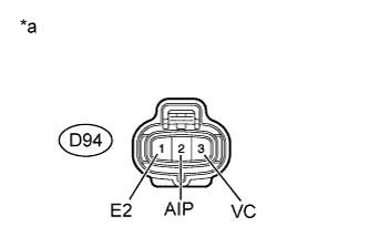
Text in Illustration *a Front view of wire harness connector
(to Air Pressure Sensor)
-
Disconnect the air pressure sensor connector.
-
Turn the ignition switch to ON.
-
Measure the voltage according to the value(s) in the table below.
Standard Voltage Tester Connection Switch Condition Specified Condition D94-3 (VC) - D94-1 (E2) Ignition switch ON 4.5 to 5.5 V
NG
REPLACE ECM Click here
OK
-
-
READ DATA LIST (PUMP PRESSURE (ABSOLUTE))
-
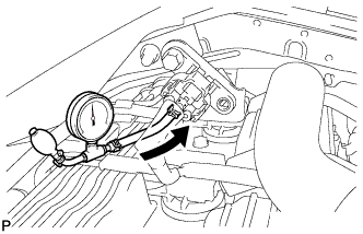
Connect a pressure gauge to the air pressure sensor as shown in the illustration.
-
Connect the intelligent tester to the DLC3.
-
Turn the ignition switch to ON.
-
Turn the tester on.
-
Enter the following menus: Powertrain / Engine and ECT / Data List / Air pump pressure (absolute).
-
Check that the pressure displayed on the intelligent tester fluctuates when applying the pressure to the air pressure sensor with the pressure gauge.
OK Pressure fluctuates in response to pressure applied with pressure gauge. Tech Tips
The intelligent tester displays the air pump pressure (Air pump pressure (absolute)) as absolute pressure.
NG
REPLACE AIR PRESSURE SENSOR Click here
OK 
REPLACE ECM Click here
-