SFI SYSTEM (w/ Secondary Air Injection System), Diagnostic DTC:P2238, P2239, P2252, P2253

| DTC Code | DTC Name |
|---|---|
| P2238 | Oxygen (A/F) Sensor Pumping Current Circuit Low (Bank 1 Sensor 1) |
| P2239 | Oxygen (A/F) Sensor Pumping Current Circuit High (Bank 1 Sensor 1) |
| P2252 | Oxygen (A/F) Sensor Reference Ground Circuit Low (Bank 1 Sensor 1) |
| P2253 | Oxygen (A/F) Sensor Reference Ground Circuit High (Bank 1 Sensor 1) |
DESCRIPTION
Refer to DTC P2195 Click here.
| DTC No. | DTC Detecting Condition | Trouble Area |
|---|---|---|
| P2238 | A/F sensor circuit low |
|
|
|
|
|
||
| P2239 | A/F sensor circuit high |
|
|
|
|
|
||
| P2252 |
|
|
| P2253 |
|
WIRING DIAGRAM
Refer to DTC P2195 Click here.
INSPECTION PROCEDURE
Tech Tips
Malfunctioning areas can be identified by performing the Control the Injection Volume for A/F Sensor operation provided in the Active Test. The Control the Injection Volume for A/F Sensor function can help determine whether the Air-Fuel Ratio (A/F) sensor, Heated Oxygen (HO2) sensor and other potential trouble areas are malfunctioning.
The following instructions describe how to conduct the Control the Injection Volume for A/F Sensor operation using an intelligent tester.
-
Connect an intelligent tester to the DLC3.
-
Start the engine and turn the tester ON.
-
Warm up the engine at an engine speed of 2,500 rpm for approximately 90 seconds.
-
On the tester, select the following menu items: Powertrain / Engine and ECT / Active Test / Control the Injection Volume for A/F Sensor.
-
Perform the Control the Injection Volume for A/F Sensor operation with the engine in an idling condition (press the RIGHT or LEFT button to change the fuel injection volume).
-
Monitor the voltage outputs of the A/F and HO2 sensors (AFS Voltage B1S1 and O2S B1S2) displayed on the tester.
Tech Tips
-
The Control the Injection Volume for A/F Sensor operation lowers the fuel injection volume by 12.5 % or increases the injection volume by 25 %.
-
Each sensor reacts in accordance with increases and decreases in the fuel injection volume.
| Voltage | ||||||||||||||||||||
|---|---|---|---|---|---|---|---|---|---|---|---|---|---|---|---|---|---|---|---|---|
|
Note
The Air-Fuel Ratio (A/F) sensor has an output delay of a few seconds and the Heated Oxygen (HO2) sensor has a maximum output delay of approximately 20 seconds.
| Case | A/F Sensor (Sensor 1) Output Voltage |
HO2 Sensor (Sensor 2) Output Voltage |
Mainly Suspected Trouble Areas | ||
|---|---|---|---|---|---|
| 1 | Injection volume +25 % -12.5 % |
 |
Injection volume +25 % -12.5 % |
|
- |
| Output voltage More than 3.4 V Less than 3.1 V |
 |
Output voltage More than 0.5 V Less than 0.4 V |
 |
||
| 2 | Injection volume +25 % -12.5 % |
|
Injection volume +25 % -12.5 % |
|
|
| Output voltage Almost no reaction |
 |
Output voltage More than 0.5 V Less than 0.4 V |
|
||
| 3 | Injection volume +25 % -12.5 % |
|
Injection volume +25 % -12.5 % |
|
|
| Output voltage More than 3.4 V Less than 3.1 V |
|
Output voltage Almost no reaction |
|
||
| 4 | Injection volume +25 % -12.5 % |
|
Injection volume +25 % -12.5 % |
|
(Air-fuel ratio extremely lean or rich) |
| Output voltage Almost no reaction |
|
Output voltage Almost no reaction |
|
||
-
Following the Control the Injection Volume for A/F Sensor procedure enables technicians to check and graph the voltage outputs of both the A/F and HO2 sensors.
-
To display the graph, select the following menu items on the tester: Powertrain / Engine and ECT / Active Test / Control the Injection Volume for A/F Sensor / User Data / AFS Voltage B1S1 and O2S B1S2.
Tech Tips
-
DTC P2A00 may be set when the air-fuel ratio is stuck rich or lean.
-
A low A/F sensor voltage could be caused by a rich air-fuel mixture. Check for conditions that would cause the engine to run rich.
-
A high A/F sensor voltage could be caused by a lean air-fuel mixture. Check for conditions that would cause the engine to run lean.
-
Read freeze frame data using an intelligent tester. The ECM records vehicle and driving condition information as freeze frame data the moment a DTC is stored. When troubleshooting, freeze frame data can be helpful in determining whether the vehicle was running or stopped, whether the engine was warmed up or not, whether the air-fuel ratio was lean or rich, as well as other data recorded at the time of a malfunction.
PROCEDURE
-
INSPECT AIR FUEL RATIO SENSOR (RESISTANCE OF A/F SENSOR HEATER)
-
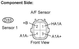
Disconnect the D33 Air-Fuel Ratio (A/F) sensor connector.
-
Measure the resistance between the terminals of the A/F sensor connector.
Resistance Tester Connections Specified Conditions HA1A (1) - +B (2) 1.8 Ω to 3.4 Ω at 20°C (68°F) HA1A (1) - A1A- (4) 10 kΩ or higher -
Reconnect the A/F sensor connector.
NG 
REPLACE AIR FUEL RATIO SENSOR
OK 
-
-
INSPECT INTEGRATION NO.1 RELAY (A/F HEATER RELAY)
-
Remove the integration relay from the engine room R/B No.1.
-
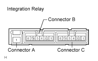
Check the integration relay (A/F HEATER relay).
Resistance Tester Connections Specified Conditions A1 - C4 10 kΩ or higher A1 - C4 Below 1 Ω
(when battery voltage applied to terminals C2 and C3)
-
Reinstall the integration relay.
NG
REPLACE INTEGRATION NO.1 RELAY
OK
-
-
CHECK HARNESS AND CONNECTOR (ECM - A/F SENSOR)
-
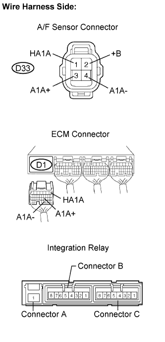
Check the harness and connectors between the ECM and A/F sensor.
-
Disconnect the D33 A/F sensor connector.
-
Disconnect the D1 ECM connector.
-
Measure the resistance.
Resistance (Check for open) Tester Connections Specified Conditions HA1A (D33-1) - HA1A (D1-1) Below 1 Ω Resistance (Check for short) Tester Connections Specified Conditions HA1A (D33-1) or HA1A (D1-1) - Body ground 10 kΩ or higher -
Reconnect the A/F sensor connector.
-
Reconnect the ECM connector.
-
-
Check the harness and connector between the A/F sensor and integration relay.
-
Disconnect the D33 A/F sensor connector.
-
Disconnect the integration relay connector.
-
Measure the resistance.
Resistance (Check for open) Tester Connections Specified Conditions +B (D33-2) - Integration relay (C4) Below 1 Ω Resistance (Check for short) Tester Connections Specified Conditions +B (D33-2) or Integration relay (C4) - Body ground 10 kΩ or higher -
Reconnect the A/F sensor connect.
-
Reconnect the integration relay connector.
-
NG
REPAIR OR REPLACE HARNESS OR CONNECTOR
OK 
REPLACE ECM
-