SFI SYSTEM (w/ Secondary Air Injection System), Diagnostic DTC:P2237, P2238, P2239, P2252, P2253

| DTC Code | DTC Name |
|---|---|
| P2237 | Oxygen (A/F) Sensor Pumping Current Circuit / Open (Bank 1 Sensor 1) |
| P2238 | Oxygen (A/F) Sensor Pumping Current Circuit Low (Bank 1 Sensor 1) |
| P2239 | Oxygen (A/F) Sensor Pumping Current Circuit High (Bank 1 Sensor 1) |
| P2252 | Oxygen (A/F) Sensor Reference Ground Circuit Low (Bank 1 Sensor 1) |
| P2253 | Oxygen (A/F) Sensor Reference Ground Circuit High (Bank 1 Sensor 1) |
DESCRIPTION
Refer to DTC P2195 Click here.
| DTC No. | DTC Detection Condition | Trouble Area |
|---|---|---|
| P2237 | An open in the circuit between terminals A1A+ and A1A- of the air fuel ratio sensor while the engine is running (2 trip detection logic). |
|
| P2238 | One of the following conditions is met (2 trip detection logic):
|
|
| P2239 | The A1A+ voltage is higher than 4.5 V (2 trip detection logic). |
|
| P2252 | The A1A- voltage is 0.5 V or less (2 trip detection logic). |
|
| P2253 | The A1A- voltage is higher than 4.5 V (2 trip detection logic). |
|
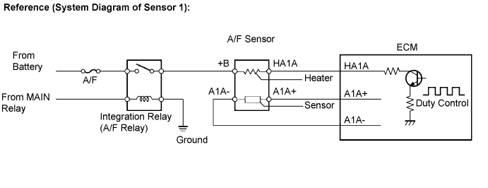
WIRING DIAGRAM
Refer to DTC P2195 Click here.
INSPECTION PROCEDURE
Tech Tips
Read freeze frame data using the intelligent tester. Freeze frame data records the engine condition when malfunctions are detected. When troubleshooting, freeze frame data can help determine if the vehicle was moving or stationary, if the engine was warmed up or not, if the air fuel ratio was lean or rich, and other data from the time the malfunction occurred.
PROCEDURE
-
CHECK HARNESS AND CONNECTOR (AIR FUEL RATIO SENSOR - ECM)
-
Disconnect the air fuel ratio sensor connector.
-
Disconnect the ECM connector.
-
Measure the resistance.
Resistance (Check for open) Tester Connections Condition Specified Conditions D33-1 (HA1A) - D1-1 (HA1A) Always Below 1 Ω D33-3 (A1A+) - D1-21 (A1A+) Always Below 1 Ω D33-4 (A1A-) - D1-31 (A1A-) Always Below 1 Ω Resistance (Check for short) Tester Connections Condition Specified Conditions D33-1 (HA1A) or D1-1 (HA1A) - Body ground Always 10 kΩ or higher D33-3 (A1A+) or D1-21 (A1A+) - Body ground Always 10 kΩ or higher D33-4 (A1A-) or D1-31 (A1A-) - Body ground Always 10 kΩ or higher -
Reconnect the ECM connector.
-
Reconnect the air fuel ratio sensor connector.
NG 
REPAIR OR REPLACE HARNESS OR CONNECTOR (AIR FUEL RATIO SENSOR - ECM)
OK 
-
-
REPLACE AIR FUEL RATIO SENSOR
-
Replace the air fuel ratio sensor.
NEXT
-
-
CHECK WHETHER DTC OUTPUT RECURS (DTC P2237, P2238, P2239, P2252 OR P2253)
-
Connect the intelligent tester to the DLC3.
-
Turn the ignition switch to ON.
-
Turn the tester on.
-
Clear the DTCs Click here.
-
Start the engine.
-
Allow the engine to idle for 5 minutes or more.
-
Enter the following menus: Powertrain / Engine and ECT / DTC.
-
Read the DTCs (Pending DTCs).
Result Result Proceed to DTC is not output A DTC P2237, P2238, P2239, P2252 or P2253 is output B
B
REPLACE ECM
A 
END
-