SFI SYSTEM (w/o Secondary Air Injection System) FREEZE FRAME DATA

-
DESCRIPTION
Freeze frame data records the engine conditions (fuel system information, calculated load, engine coolant temperature, fuel trim, engine speed, vehicle speed, etc.) when a malfunction is detected. When troubleshooting, it can help determine if the vehicle was moving or stationary, if the engine was warmed up or not, if the air-fuel ratio was Lean or Rich, and other data from the time the malfunction occurred.
Tech Tips
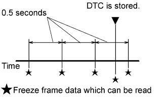
If it is impossible to duplicate the problem even though a DTC is output, confirm the freeze frame data.
The ECM records engine conditions in the form of freeze frame data every 0.5 seconds. Using the intelligent tester, 5 separate sets of freeze frame data can be checked.
-
3 data sets from before the DTC was stored
-
1 data set from when the DTC was stored
-
1 data set from after the DTC was stored
These data sets can be used to simulate the condition of the vehicle from around the time of the occurrence of the malfunction. The data may assist in identifying the cause of the malfunction, and in judging whether it was temporary or not.
-
-
LIST OF FREEZE FRAME DATA
Tester Display Measurement Item Diagnostic Note Vehicle Speed Vehicle speed Speed indicated on the speedometer. Engine Speed Engine speed - Calculate Load Calculated load Load calculated by the ECM. MAF Mass air flow volume If the value is approximately 0.0 gm/s:
-
Mass air flow meter power source circuit is open.
-
VG circuit is open or shorted.
If the value is 160.0 gm/s or more:
-
E2G circuit is open.
Atmosphere Pressure Atmospheric pressure - Coolant Temp Engine coolant temperature If the value is -40°C, the sensor circuit is open.
If the value is 140°C, the sensor circuit is shorted.
Intake Air Intake air temperature If the value is -40°C, the sensor circuit is open.
If the value is 140°C, the sensor circuit is shorted.
Engine Run Time Accumulated engine running time - Radiator Coolant Temp Engine coolant (radiator) temperature If the value is -40°C, the sensor circuit is open.
If the value is 140°C, the sensor circuit is shorted.
Initial Engine Coolant Temp Initial engine coolant temperature - Initial Intake Air Temp Initial intake air temperature - Battery Voltage Battery voltage - Accel Sens. No. 1 Volt % Absolute accelerator pedal position No. 1 - Accel Sens. No. 2 Volt % Absolute accelerator pedal position No. 2 - Throttle Sensor Volt % Throttle sensor position Read the value with the ignition switch ON (do not start engine). Throttle Sensor #2 Volt % Throttle sensor position #2 Read the value with the ignition switch ON (do not start engine). Throttle Sensor Position Throttle position Read the value with the ignition switch ON (do not start engine). Throttle Motor DUTY Throttle actuator - Injector (Port) Injection period of No. 1 cylinder - Injection Volum (Cylinder 1) Injection volume - Fuel Pump/Speed Status Fuel pump status - Evap Purge Flow* Ratio of evaporative purge flow to intake air volume - Purge Density Learn Value* Purge density learned value - EVAP Purge VSV* EVAP purge VSV - Target Air-Fuel Ratio* Air-fuel ratio - O2S B1S1* Heated oxygen sensor output Performing the Control the Injection Volume or Control the Injection Volume for A/F Sensor function of the Active Test enables the technician to check the output voltage of the heated oxygen sensor. Short FT #1* Short-term fuel trim Short-term fuel compensation is used to maintain the heated oxygen sensor at the stoichiometric air-fuel ratio. Long FT #1* Long-term fuel trim Overall fuel compensation is carried out in the long term to compensate for a continual deviation of the short-term fuel trim from the central value. Fuel System Status #1* Fuel system status (Bank 1)
-
OL (Open Loop): Has not yet satisfied the conditions to go closed loop.
-
CL (Closed Loop): Using the heated oxygen sensor as feedback for fuel control.
-
OLDrive: Open loop due to driving conditions (fuel enrichment).
-
OLFault: Open loop due to a detected system fault.
-
CLFault: Closed loop but the heated oxygen sensor, which is used for fuel control, is malfunctioning.
Fuel System Status #2* Fuel system status (Bank 2) - O2FT B1S1* Fuel trim at heated oxygen sensor - IGN Advance Ignition timing advance for No. 1 cylinder - Knock Feedback Value Knocking feedback value - Knock Correct Learn Value Knocking correction learned value - VVT Control Status #1 VVT control status - Starter Signal Starter signal - Power Steering Signal Power steering signal - Power Steer. Sig. Record Power steering signal This signal status usually ON until ignition switch turned to OFF Stop Light Switch Stop light switch - A/C Signal A/C signal - Closed Throttle Position SW Closed throttle position switch - Fuel Cut Condition Fuel cut condition - Immobiliser Communication Immobiliser communication - Electrical Load Signal Electrical load signal - Time after DTC Cleared Cumulative time after DTCs cleared - Distance from DTC Cleared Accumulated distance driven after DTCs cleared - Warmup Cycle Cleared DTC Warmup cycles after DTCs cleared - TC and TE1 TC and CG (TE1) terminals of DLC3 - Electric Fan Motor Electric fan motor status - Idle Fuel Cut Fuel cut at idle ON: The throttle valve is fully closed and the engine speed is more than 2800 rpm. FC TAU Fuel cut during very light load Fuel cut is being performed under a very light load to prevent the engine combustion from becoming incomplete. *: Except leaded gasoline specification vehicle
-