SFI SYSTEM (w/o Secondary Air Injection System) DIAGNOSIS SYSTEM

-
M-OBD (EXCEPT EUROPEAN SPEC.)
-
When troubleshooting Multiplex On-Board Diagnostic (M-OBD) vehicles, the vehicle must be connected to the Intelligent Tester. Various data output from the ECM can then be read.
-

OBD II regulations require that the vehicle's on-board computer illuminates the MIL on the instrument panel when the computer detects a malfunction in:
-
The emission control system/components.
-
The power train control components (which affect vehicle emissions).
-
The computer.
-
-
In addition to, the applicable DTCs are recorded in the ECM memory. If the malfunction does not recur in 3 consecutive trips, the MIL goes off automatically but the DTCs remain recorded in the ECM memory.
-
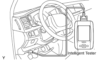
To check DTCs, connect the intelligent tester to the Data link Connector 3 (DLC3) of the vehicle.
The scan tool displays DTCs, the freeze frame data and a variety of the engine data.
The DTCs and freeze frame data can be erased with the scan tool Click here.
-
-
FREEZE FRAME DATA
-
The ECM records vehicle and driving condition information as freeze frame data the moment a DTC is stored. When troubleshooting, freeze frame data can be helpful in determining whether the vehicle was running or stopped, whether the engine was warmed up or not, whether the air-fuel ratio was lean or rich, as well as other data recorded at the time of a malfunction.
-
-
DLC3 (Data Link Connector 3)
-
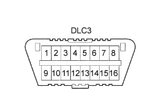
The vehicle's ECM uses the ISO 9141-2 (Euro-OBD)/ISO 14230 (M-OBD) communication protocol. The terminal arrangement of the DLC3 complies with ISO 15031-03 and matches the ISO 9141-2/ISO 14230 format.
Tech Tips
Connect the cable of the Intelligent Tester to the DLC3, turn the ignition switch to the ON position and attempt to use the intelligent tester. If the screen displays a communication error message, a problem exists on the vehicle side or the tester side.
If the communication is normal when the tool is connected to another vehicle, inspect the DLC3 on the original vehicle.
If the communication is still impossible when the tool is connected to another vehicle, the problem is probably in the tool itself. Consult the Service Department listed in the tool's instruction manual.
Symbol Terminal No. Name Reference terminal Result Condition SIL 7 Bus "+" line 5 - Signal ground Pulse generation During transmission CG 4 Chassis ground Body ground 1 Ω or less Always SG 5 Signal ground Body ground 1 Ω or less Always BAT 16 Battery positive Body ground 9 to 14 V Always CANH 6 HIGH-level CAN bus line 14 - LOW-level CAN bus line 54 to 69 Ω Ignition switch OFF CANH 6 HIGH-level CAN bus line 16 - Battery Positive 1 MΩ or higher Ignition switch OFF CANH 6 HIGH-level CAN bus line 4 - Chassis ground 1 kΩ or higher Ignition switch OFF CANL 14 LOW-level CAN bus line 16 - Battery positive 1 MΩ or higher Ignition switch OFF CANL 14 LOW-level CAN bus line 4 - Chassis ground 1 kΩ or higher Ignition switch OFF
-
-
INSPECT BATTERY VOLTAGE
If voltage is below 11 V, replace the battery before proceeding.
-
CHECK MIL
-
Check that the MIL illuminates when turning the ignition switch to the ON position.
If the MIL does not illuminate, there is a problem in the MIL circuit Click here.
-
When the engine is started, the MIL should go off.
-