SFI SYSTEM (w/ Secondary Air Injection System), Diagnostic DTC:P0500

| DTC Code | DTC Name |
|---|---|
| P0500 | Vehicle Speed Sensor "A" |
DESCRIPTION
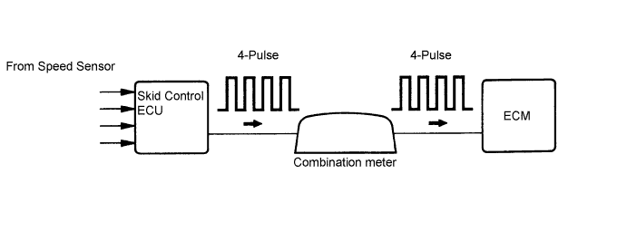
Vehicles, which are equipped with ABS (Anti-lock Brake System), detect the vehicle speed using the skid control ECU and wheel speed sensor. The wheel speed sensor monitors the wheel rotation speed and sends a signal to the skid control ECU. The skid control ECU converts the wheel speed signal into a 4-pulse signal and transmits it to the ECM via the combination meter. The ECM determines the vehicle speed based on the frequency of the pulse signal.
| DTC No. | DTC Detection Conditions | Trouble Areas |
|---|---|---|
| P0500 |
|
|
MONITOR DESCRIPTION
The ECM assumes that the vehicle is being driven, while the vehicle speed sensor signal is being transmitted by the combination meter. If there is no signal from the combination meter, despite the ECM detecting the speed signal from the speed sensor No.2, the ECM interprets this as a malfunction in the speed signal circuit. The ECM then illuminates the MIL and sets the DTC.
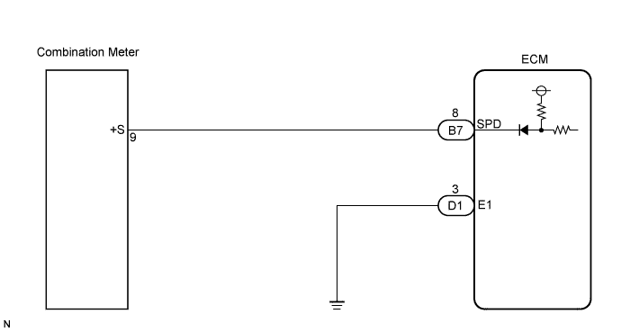
WIRING DIAGRAM
INSPECTION PROCEDURE
Tech Tips
Read freeze frame data using an intelligent tester. The ECM records vehicle and driving condition information as freeze frame data the moment a DTC is stored. When troubleshooting, freeze frame data can be helpful in determining whether the vehicle was running or stopped, whether the engine was warmed up or not, whether the air-fuel ratio was lean or rich, as well as other data recorded at the time of a malfunction.
PROCEDURE
-
CHECK OPERATION OF SPEEDOMETER
-
Drive the vehicle and check if the operation of the speedometer in the combination meter is normal.
Tech Tips
The vehicle speed sensor is operating normally if the speedometer reading is normal.
NG 
CHECK SPEEDOMETER CIRCUIT
OK 
-
-
INSPECT ECM (SPD VOLTAGE)
-
Shift the transmission gear selector lever to the neutral position.
-
Jack up the vehicle.
-
Turn the ignition switch to the ON position.
-
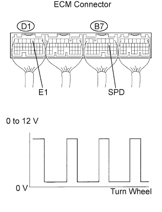
Measure the voltage between the terminals of the ECM connectors as the wheel is turned slowly.
Standard Tester Connections Specified Conditions SPD (B7-8) - E1 (D1-3) Voltage generated intermittently Tech Tips
The output voltage should fluctuate up and down similarly to the diagram in the illustration when the wheel is turned slowly.
NG
REPAIR OR REPLACE HARNESS OR CONNECTOR
OK 
REPLACE ECM
-