SFI SYSTEM (w/ Secondary Air Injection System), Diagnostic DTC:P0443

| DTC Code | DTC Name |
|---|---|
| P0443 | Evaporative Emission Control System Purge Control Valve Circuit |
DESCRIPTION
In order to reduce hydrocarbon (HC) emissions, evaporated fuel from the fuel tank is routed through the charcoal canister to the intake manifold for combustion in the cylinders.
The ECM changes the duty signal to the EVAP VSV so that the intake of HC emissions is appropriate for the driving conditions (engine load, engine speed, vehicle speed, etc.) after the engine is warmed up.
| DTC No. | DTC Detection Condition | Trouble Area |
|---|---|---|
| P0443 | Proper response to ECM command does not occur (1 trip detection logic) |
|
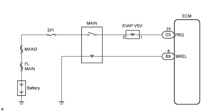
WIRING DIAGRAM
INSPECTION PROCEDURE
Tech Tips
Read freeze frame data using the intelligent tester. The ECM records vehicle and driving condition information as freeze frame data the moment a DTC is stored. When troubleshooting, freeze frame data can be helpful in determining whether the vehicle was running or stopped, whether the engine was warmed up or not, whether the air-fuel ratio was lean or rich, as well as other data recorded at the time of a malfunction.
PROCEDURE
-
PERFORM ACTIVE TEST USING INTELLIGENT TESTER (EVAP VSV)
-
Disconnect the vacuum hose of the EVAP VSV.
-
Connect the intelligent tester to the DLC3.
-
Start the engine and turn the intelligent tester ON.
-
Select the following menu items: Powertrain / Engine and ECT /Active Test / Activate the VSV for EVAP Control.
-
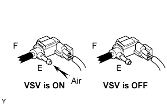
Check if the disconnected port applies suction to your finger when operating the EVAP VSV using the intelligent tester.
Standard Tester Operation Specified condition VSV is ON Applies suction to your finger VSV is OFF Applies no suction to your finger -
Reconnect the vacuum hose.
OK 
CHECK FOR INTERMITTENT PROBLEMS
NG 
-
-
INSPECT ECM (CHECK VOLTAGE)
-
Turn the ignition switch to the ON position.
-
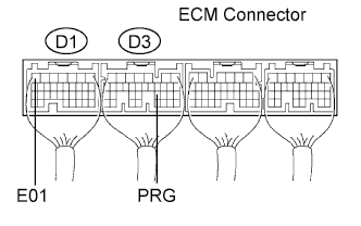
Measure the voltage according to the value(s) in the table below.
Voltage Tester Connection Specified Condition PRG (D3-23) - E01 (D1-7) 9 to 14 V
OK
REPLACE ECM
NG
-
-
CHECK OPERATION OF EVAP VSV
OK Air flows when the battery voltage is applied to the EVAP VSV.
NG
REPLACE EVAP VSV
OK
-
CHECK HARNESS AND CONNECTOR (ECM - EVAP VSV)
-
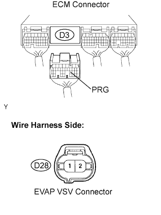
Disconnect the D3 ECM connector.
-
Disconnect the D28 EVAP VSV connector.
-
Measure the resistance according to the value(s) in the table below.
Resistance (Check for open) Tester Connection Specified Condition EVAP VSV (D28-1) - PRG (D3-23) Below 1 Ω Resistance (Check for short) Tester Connection Specified Condition EVAP VSV (D28-1) or PRG (D3-23) -
Body ground
10 kΩ or higher -
Reconnect the ECM connector.
-
Reconnect the EVAP VSV connector.
NG
REPAIR OR REPLACE HARNESS OR CONNECTOR
OK
-
-
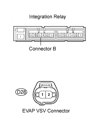
CHECK HARNESS AND CONNECTOR (EVAP VSV - INTEGRATION RELAY)
-
Remove the integration relay from the engine room R/B No.1.
-
Disconnect the D28 EVAP VSV connector.
-
Measure the resistance according to the value(s) in the table below.
Resistance (Check for open) Tester Connection Specified Condition EVAP VSV (D28-2) - integration relay (B4) Below 1 Ω Resistance (Check for short) Tester Connection Specified Condition EVAP VSV (D28-2) or integration relay (B4) - Body ground 10 kΩ or higher -
Reinstall the integration relay.
-
Reconnect the EVAP VSV connector.
NG
REPAIR OR REPLACE HARNESS OR CONNECTOR
OK 
INSPECT ECM POWER SOURCE CIRCUIT
-