SFI SYSTEM (w/ Secondary Air Injection System), Diagnostic DTC:P0418

| DTC Code | DTC Name |
|---|---|
| P0418 | Secondary Air Injection System Control "A" Circuit |
DESCRIPTION
Refer to DTC P0412 Click here.
| DTC No. | DTC Detection Condition | Trouble Area |
|---|---|---|
| P0418 |
|
|
|
|
MONITOR DESCRIPTION
Air Injection Control Driver (AID) detects an open or short in the air pump and Air Switching Valve (ASV) circuit according to the terminal voltage and sends a signal as the diagnostic information to the ECM.
After a cold engine start, the ECM transmits command signals to the AID to drive the air pump and ASV.
The AID outputs the air pump malfunction signal to the ECM if: 1) the voltage at the AID terminal relating to the air pump is low despite the AID receiving command signals from the ECM to drive the air pump or 2) the voltage at the AID terminal relating to the air pump is high despite the AID receiving no command signals from the ECM to drive the air pump.
The ECM sets the DTC based on the diagnostic signal from the AID.
WIRING DIAGRAM
Refer to DTC P0412 Click here.
INSPECTION PROCEDURE
Tech Tips
Read freeze frame data using the intelligent tester. Freeze frame data records the engine condition when malfunctions are detected. When troubleshooting, freeze frame data can help determine if the vehicle was moving or stationary, if the engine was warmed up or not, if the air fuel ratio was lean or rich, and other data from the time the malfunction occurred.
PROCEDURE
-
CHECK HARNESS AND CONNECTOR (AIR PUMP ASSEMBLY - BODY GROUND)
-
Disconnect the air pump connector.
-
Measure the resistance according to the value(s) in the table below.
Resistance (Check for Open) Tester Connection Condition Specified Condition B17-1 - Body ground Always Below 1 Ω -
Reconnect the air pump connector.
NG 
REPAIR OR REPLACE HARNESS OR CONNECTOR
OK 
-
-
CHECK HARNESS AND CONNECTOR (AIR PUMP ASSEMBLY - AIR INJECTION CONTROL DRIVER, BATTERY - AIR INJECTION CONTROL DRIVER)
-
Disconnect the cable from the negative (-) battery terminal.
-
Disconnect the cable from the positive (+) battery terminal.
-
Disconnect the Air Injection Control Driver (AID) connector.
-
Disconnect the air pump connector.
-
Measure the resistance according to the value(s) in the table below.
Resistance (Check for Open) Tester Connection Condition Specified Condition B17-2 - B14-2 (VP) Always Below 1 Ω B14-1 (BATT) - positive (+) battery terminal Always Below 1 Ω Resistance (Check for Short) Tester Connection Condition Specified Condition B17-2 or B14-2 (VP) - Body Ground Always 10 kΩ or higher B14-1 (BATT) or positive (+) battery terminal - Body ground Always 10 kΩ or higher -
Reconnect the air pump connector.
-
Reconnect the AID connector.
-
Connect the cable to the positive (+) battery terminal.
-
Connect the cable to the negative (-) battery terminal.
NG
REPAIR OR REPLACE HARNESS OR CONNECTOR
OK
-
-
INSPECT AIR PUMP ASSEMBLY
-
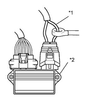
Text in Illustration *1 Air Pump Wire *2 Air Injection Control Driver Connect the intelligent tester to the DLC3.
-
Connect the 400 A probe of an ammeter to the (+) wire of the air pump.
-
Turn the ignition switch to ON and turn the tester on.
-
Enter the following menus: Powertrain / Engine and ECT / Data List / Coolant Temp, Intake Air, Secondary Air Control VSV, and 2nd Air System Status.
-
Cool the engine down until the engine coolant temperature and the ambient temperature are almost the same.
-
Crank the engine and measure the current when the air pump is on and off.
Standard Current AI System (Air Pump) Operation Condition Specified Condition ON
(soon after the cold engine starts)
Always 10 to 40 A OFF
(engine is idling)
Always Below 1 A Tech Tips
Check whether the air pump operating sound occurs when the AI system operates (soon after cold engine starts). If the air pump operating sound is not confirmed, the pump may be defective.
NG 
REPLACE AIR PUMP ASSEMBLY Click here
OK 
REPLACE AIR INJECTION CONTROL DRIVER
-
-
REPLACE AIR PUMP ASSEMBLY
-
Replace the air pump assembly Click here.
NEXT
-
-
CHECK WHETHER DTC OUTPUT RECURS (DTC P0418)
-
Cool the engine down until the engine coolant temperature and the ambient temperature are almost the same.
-
Connect the intelligent tester to the DLC3.
-
Turn the ignition switch to ON and turn the tester on.
-
Enter the following menus: Powertrain / Engine and ECT / Data List / Secondary Air Control VSV, and 2nd Air System Status.
-
Start the engine and confirm that the AI system has been operated.
-
Enter the following menus: Powertrain / Engine and ECT / DTC.
-
Read DTCs.
OK No DTC output.
NG
REPLACE AIR INJECTION CONTROL DRIVER
OK
END
-