SFI SYSTEM (w/ Secondary Air Injection System), Diagnostic DTC:P0412

| DTC Code | DTC Name |
|---|---|
| P0412 | Secondary Air Injection System Switching Valve "A" Circuit |
DESCRIPTION
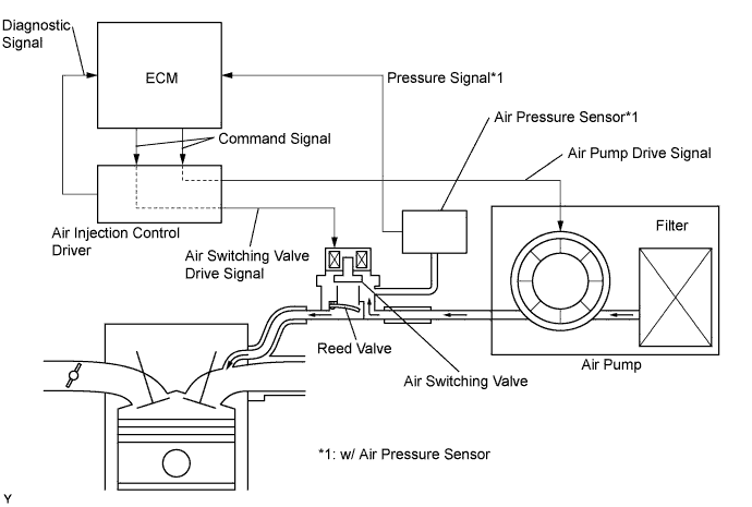
The secondary air injection system injects air into the exhaust port of the cylinder head using an electric air pump, starting when the engine is started cold and operating until the catalyst warms up, in order to promote combustion of unburned fuel and decrease the amount of hydrocarbons (HC) and carbon monoxide (CO) in the exhaust gas.
| DTC No. | DTC Detection Condition | Trouble Area |
|---|---|---|
| P0412 |
|
|
| P0412 |
|
|
MONITOR DESCRIPTION
The Air Injection Control Driver (AID) detects open and short circuits according to the voltages of the air pump terminal and the Air Switching Valve (ASV) terminal, and transmits diagnostic information as a signal to the ECM.
For a short time after cold engine starts, the ECM transmits command signals to the AID to drive the air pump and ASV.
The AID transmits an ASV malfunction signal to the ECM if either of the following conditions is met:
-
The voltage at the AID terminal relating to the ASV is low despite the AID receiving command signals from the ECM to drive the ASV.
-
The voltage at the AID terminal relating to the ASV is high despite the AID receiving no command signals from the ECM to drive the ASV.
The ECM sets the DTC based on diagnostic signals from the AID.
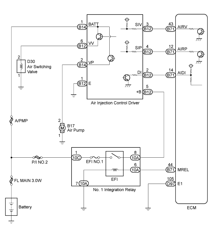
WIRING DIAGRAM
INSPECTION PROCEDURE
Tech Tips
Read freeze frame data using the intelligent tester. Freeze frame data records the engine condition when malfunctions are detected. When troubleshooting, freeze frame data can help determine if the vehicle was moving or stationary, if the engine was warmed up or not, if the air-fuel ratio was lean or rich, and other data from the time the malfunction occurred.
PROCEDURE
-
INSPECT AIR SWITCHING VALVE ASSEMBLY
-
Inspect the air switching valve assembly Click here.
NG 
REPLACE AIR SWITCHING VALVE ASSEMBLY Click here
OK 
-
-
CHECK HARNESS AND CONNECTOR (AIR SWITCHING VALVE - BODY GROUND)
-
Disconnect the air switching valve connector.
-
Measure the resistance according to the value(s) in the table below.
Standard Resistance Tester Connection Condition Specified Condition D30-1 - Body ground Always Below 1 Ω
NG
REPAIR OR REPLACE HARNESS OR CONNECTOR
OK
-
-
CHECK HARNESS AND CONNECTOR (AIR SWITCHING VALVE - AIR INJECTION CONTROL DRIVER)
-
Disconnect the air switching valve connector.
-
Disconnect the air injection control driver connector.
-
Measure the resistance according to the value(s) in the table below.
Standard Resistance Tester Connection Condition Specified Condition D30-2 - B12-6 (VV) Always Below 1 Ω D30-2 or B12-6 (VV) - Body ground Always 10 kΩ or higher
NG
REPAIR OR REPLACE HARNESS OR CONNECTOR
OK 
REPLACE AIR INJECTION CONTROL DRIVER
-