SFI SYSTEM (w/ Secondary Air Injection System), Diagnostic DTC:P0340, P0341

| DTC Code | DTC Name |
|---|---|
| P0340 | Camshaft Position Sensor "A" Circuit (Bank 1 or Single Sensor) |
| P0341 | Camshaft Position Sensor "A" Circuit Range / Performance (Bank 1 or Single Sensor) |
DESCRIPTION
The Camshaft Position (CMP) sensor consists of a magnet and an iron core which is wrapped with copper wire, and is installed onto the cylinder head. When the camshaft rotates, each of 3 teeth on the camshaft passes through the CMP sensor. This activates the internal magnet in the sensor, generating a voltage in the copper wire. The camshaft rotation is synchronized with the crankshaft rotation. When the crankshaft turns twice, the voltage is generated 3 times in the CMP sensor. The generated voltage in the sensor acts as a signal, allowing the ECM to locate the camshaft position. This signal is then used to control ignition timing, fuel injection timing, and the VVT system.
| DTC No. | DTC Detection Conditions | Trouble Areas |
|---|---|---|
| P0340 |
|
|
| P0341 | When crankshaft rotates twice, Camshaft Position (CMP) sensor signal input to ECM 12 times or more (1 trip detection logic) |
|
Tech Tips
-
DTC P0340 indicates a malfunction relating to the CMP sensor (+) circuit (the wire harness between the ECM and CMP sensor, and the CMP sensor itself).
-
DTC P0341 indicates a malfunction relating to the CMP sensor (-) circuit (the wire harness between the ECM and CMP sensor, and the CMP sensor itself).
Tech Tips
-
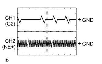
The correct waveform is shown in the illustration.
-
G2 stands for the CMP sensor signal, and NE+ stands for the Crankshaft Position (CKP) sensor signal.
| Items | Contents |
| Terminals | CH1: G2 - NE- CH2: NE+ - NE- |
| Equipment Settings | 5 V/Division, 20 ms/Division |
| Conditions | Cranking or idling |
MONITOR DESCRIPTION
If no signal is transmitted by the CMP sensor despite the engine revolving, or the rotation of the camshaft and the crankshaft is not synchronized, the ECM interprets this as a malfunction of the sensor.
If the malfunction is not repaired successfully, a DTC is set 10 seconds after the engine is next started.
WIRING DIAGRAM
Refer to DTC P0335 Click here.
INSPECTION PROCEDURE
Tech Tips
Read freeze frame data using an intelligent tester. The ECM records vehicle and driving condition information as freeze frame data the moment a DTC is stored. When troubleshooting, freeze frame data can be helpful in determining whether the vehicle was running or stopped, whether the engine was warmed up or not, whether the air-fuel ratio was lean or rich, as well as other data recorded at the time of a malfunction.
PROCEDURE
-
INSPECT CAMSHAFT POSITION SENSOR (RESISTANCE)
-
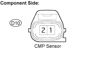
Disconnect the D10 Camshaft Position (CMP) sensor connector.
-
Measure the resistance between terminals 1 and 2.
Resistance Tester Connections Specified Conditions 1 - 2 835 to 1,400 Ω at cold 1 - 2 1,060 to 1,645 Ω at hot Tech Tips
Terms "cold" and "hot" refer to the temperature of the coils. "Cold" means approximately -10°C to 50°C (14°F to 122°F). "Hot" means approximately 50°C to 100°C (122°F to 212°F).
-
Reconnect the CMP sensor connector.
NG 
REPLACE CAMSHAFT POSITION SENSOR
OK 
-
-
CHECK HARNESS AND CONNECTOR (CAMSHAFT POSITION SENSOR - ECM)
-
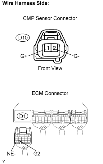
Disconnect the D10 CMP sensor connector.
-
Disconnect the D1 ECM connector.
-
Measure the resistance.
Resistance (Check for open) Tester Connections Specified Conditions G+ (D10-1) - G2 (D1-26) Below 1 Ω G- (D10-2) - NE- (D1-34) Below 1 Ω Resistance (Check for short) Tester Connections Specified Conditions G+ (D10-1) or G2 (D1-26) - Body ground 10 kΩ or higher G- (D10-2) or NE- (D1-34) - Body ground 10 kΩ or higher -
Reconnect the ECM connector.
-
Reconnect the CMP sensor connector.
NG
REPAIR OR REPLACE HARNESS OR CONNECTOR
OK
-
-
CHECK SENSOR INSTALLATION (CAMSHAFT POSITION SENSOR)
-
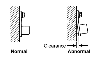
Check the CMP sensor installation condition.
OK Sensor is installed correctly.
NG
SECURELY REINSTALL SENSOR
OK
-
-
CHECK CAMSHAFT TIMING GEAR ASSEMBLY (TEETH OF SENSOR PLATE)
-
Check the teeth of the sensor plate.
OK Sensor plate teeth do not have any cracks or deformation.
NG
REPLACE CAMSHAFT TIMING GEAR ASSEMBLY
OK 
REPLACE ECM
-