SFI SYSTEM (w/ Secondary Air Injection System), Diagnostic DTC:P0335, P0339

| DTC Code | DTC Name |
|---|---|
| P0335 | Crankshaft Position Sensor "A" Circuit |
| P0339 | Crankshaft Position Sensor "A" Circuit Intermittent |
DESCRIPTION
The Crankshaft Position (CKP) sensor system consists of a CKP sensor plate and a pickup coil. The sensor plate has 34 teeth and is installed on the crankshaft. The pickup coil is made of an iron core and a magnet. The sensor plate rotates and, as each tooth passes through the pickup coil, a pulse signal is created. The pickup coil generates 34 signals per engine revolution. Based on these signals, the ECM calculates the crankshaft position and engine RPM. Using these calculations, the fuel injection time and ignition timing are controlled.
| DTC No. | DTC Detection Conditions | Trouble Areas |
|---|---|---|
| P0335 |
|
|
| P0339 |
|
|
Tech Tips
-
The correct waveform is shown in the illustration.
-
G2 stands for the Camshaft Position (CMP) sensor signal, and NE+ stands for the CKP sensor signal.
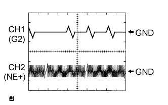
| Items | Contents |
| Terminals | CH1: G2 - NE- CH2: NE+ - NE- |
| Equipment Settings | 5 V/Division, 20 ms/Division |
| Conditions | Cranking or idling |
MONITOR DESCRIPTION
If there is no signal from the CKP sensor despite the engine revolving, the ECM interprets this as a malfunction of the sensor.
If the malfunction is not repaired successfully, a DTC is set 10 seconds after the engine is next started.
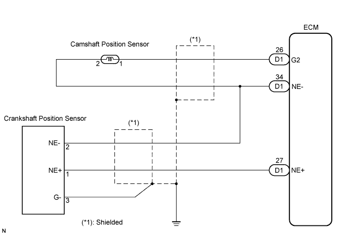
WIRING DIAGRAM
INSPECTION PROCEDURE
Tech Tips
-
If no problem is found by this diagnostic troubleshooting procedure, troubleshoot the engine mechanical systems.
-
Check the engine speed. The engine speed can be checked by using an intelligent tester. To check, perform the following procedures:
-
Connect an intelligent tester to the DLC3.
-
Start the engine.
-
Turn the tester on.
-
Select the following menu items: Powertrain / Engine and ECT / Data List / Engine Spd.
The engine speed may be indicated as zero despite the engine revolving normally. This is caused by a lack of NE signals from the Crankshaft Position (CKP) sensor. Alternatively, the engine speed may be indicated as lower than the actual engine speed, if the CKP sensor voltage output is insufficient.
-
Read freeze frame data using an intelligent tester. The ECM records vehicle and driving condition information as freeze frame data the moment a DTC is stored. When troubleshooting, freeze frame data can be helpful in determining whether the vehicle was running or stopped, whether the engine was warmed up or not, whether the air-fuel ratio was lean or rich, as well as other data recorded at the time of a malfunction.
PROCEDURE
-
INSPECT CRANKSHAFT POSITION SENSOR (RESISTANCE)
-
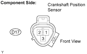
Disconnect the D17 Crankshaft Position (CKP) sensor connector.
-
Measure the resistance between terminals 1 and 2.
Resistance Tester Connections Specified Conditions 1 - 2 1,630 to 2,740 Ω at cold 1 - 2 2,065 to 3,225 Ω at hot Tech Tips
Terms "cold" and "hot" refer to the temperature of the coils. "Cold" means approximately -10°C to 50°C (14°F to 122°F). "Hot" means approximately 50°C to 100°C (122°F to 212°F).
-
Reconnect the CKP sensor connector.
NG 
REPLACE CRANKSHAFT POSITION SENSOR
OK 
-
-
CHECK HARNESS AND CONNECTOR (CRANKSHAFT POSITION SENSOR - ECM)
-
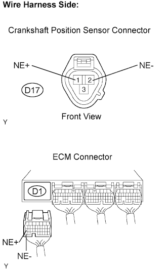
Disconnect the D17 CKP sensor connector.
-
Disconnect the D1 ECM connector.
-
Measure the resistance.
Resistance (Check for open) Tester Connections Specified Conditions NE+ (D17-1) - NE+ (D1-27) Below 1 Ω NE- (D17-2) - NE- (D1-34) Below 1 Ω Resistance (Check for short) Tester Connections Specified Conditions NE+ (D17-1) or NE+ (D1-27) - Body ground 10 kΩ or higher NE- (D17-2) or NE- (D1-34) - Body ground 10 kΩ or higher -
Reconnect the ECM connector.
-
Reconnect the CKP sensor connector.
NG
REPAIR OR REPLACE HARNESS OR CONNECTOR
OK
-
-
CHECK SENSOR INSTALLATION (CRANKSHAFT POSITION SENSOR)
-
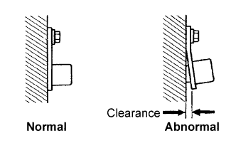
Check the CKP sensor installation condition.
OK Sensor is installed correctly
NG
SECURELY REINSTALL SENSOR
OK
-
-
CHECK CRANKSHAFT POSITION SENSOR PLATE (TEETH OF SENSOR PLATE)
-
Check the teeth of the sensor plate.
OK Sensor plate does not have any cracks or deformation.
NG
REPLACE CRANKSHAFT POSITION SENSOR PLATE
OK 
REPLACE ECM
-