SFI SYSTEM (w/ Secondary Air Injection System), Diagnostic DTC:P1613

| DTC Code | DTC Name |
|---|---|
| P1613 | Secondary Air Injection Driver Malfunction |
DESCRIPTION
Refer to DTC P0412 Click here.
| DTC No. | DTC Detection Condition | Trouble Area |
|---|---|---|
| P1613 |
|
|
| P1613 |
|
|
| P1613 |
|
|
MONITOR DESCRIPTION
After the cold engine starts, the ECM transmits command signals to the Air Injection Control Driver (AID) to drive the air pump and Air Switching Valve (ASV). The AID detects an open or short in the air pump and ASV circuit according to the AID terminal voltage and sends a signal as the diagnostic information to the ECM.
If the Secondary Air Injection (AI) system circuit or the AID itself has a malfunction, the AID sends a malfunction signal (duty signal) as a diagnostic signal to the ECM (when the system is normal, a system normal signal is sent). The ECM sets the DTC based on the diagnostic information from the AID.
The ECM sets the DTC based on the diagnostic information from the AID.
-
Example:
-
The duty ratio of the diagnostic signal from the AID is 0 or 100 % (remains at 0 V or battery voltage).
-
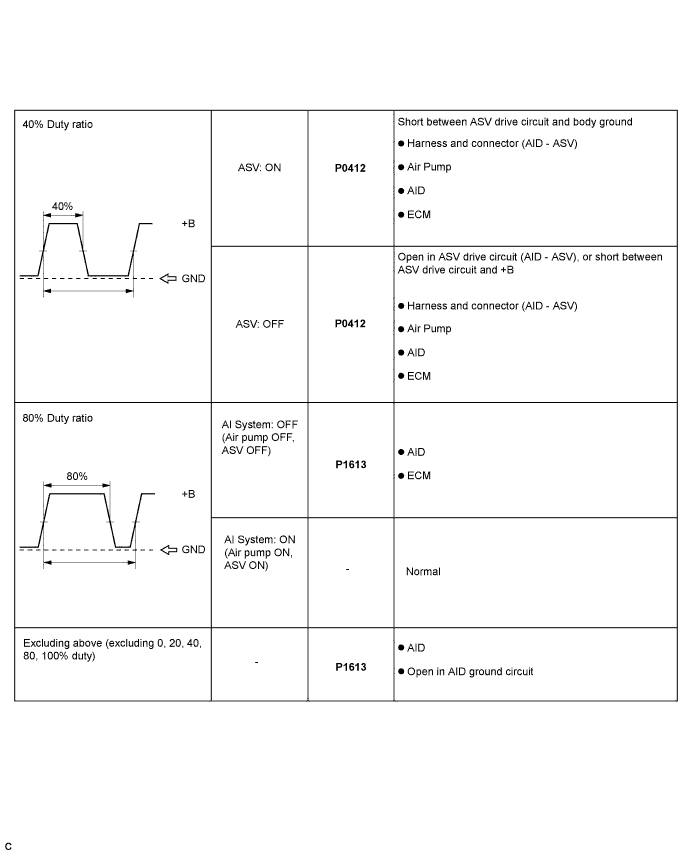
The duty ratio of the diagnostic signal from the AID is the ratio to output the impossible (excluding 0, 20, 40, 60, 80, 100 %).
-
The AID outputs the normal signal (normal duty signal: 80 %) while the system is not operating.
WIRING DIAGRAM
Refer to DTC P0412 Click here.
INSPECTION PROCEDURE
Tech Tips
The diagnostic information output from the Air Injection Control Driver (AID) can be confirmed by connecting an oscilloscope to the diagnostic information terminal of the AID.
-
Connect the intelligent tester to the DLC3.
-
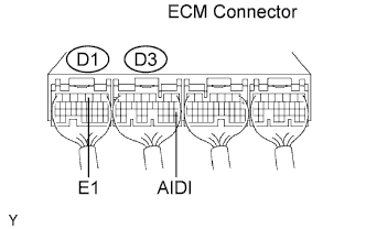
Connect an oscilloscope probe to the AIDI terminal of the ECM.
-
Turn the tester ON.
-
Enter the following menus: Powertrain / Engine and ECT / Data List / Secondary Air Control VSV and 2nd Air System Status.
-
Monitor the voltage output of the AID (duty ratio signal) when the AI system operates and does not operate.
Tech Tips
Since the AI system pumps secondary air to the exhaust port of the cylinder head for a short time after a cold engine start, if the AI system does not operate, cool the engine down until the engine coolant temperature and the ambient air temperature are almost the same.
Oscilloscope range: Items Contents Terminals CH1: AIDI (D3-20) - E1 (D1-3) Equipment Settings 5 V/Division, 20 to 40 ms/Division Conditions Idling 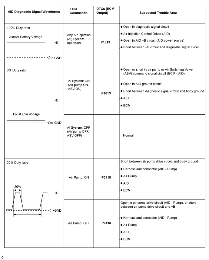
Tech Tips
Read freeze frame data using the intelligent tester. The ECM records vehicle and driving condition information as freeze frame data the moment a DTC is stored. When troubleshooting, freeze frame data can be helpful in determining whether the vehicle was running or stopped, whether the engine was warmed up or not, whether the air-fuel ratio was lean or rich, as well as other data recorded at the time of a malfunction.
PROCEDURE
-
CHECK ANY OTHER DTCS OUTPUT (IN ADDITION TO DTC P1613)
-
Connect the intelligent tester to the DLC3.
-
Turn the ignition switch to the ON position and turn the tester ON.
-
Select the following menu items: Powertrain / Engine and ECT / DTC.
-
Read DTCs.
Result Display (DTC Output) Proceed To P0163 A P0163 and other DTCs B Tech Tips
If any DTCs other than P1613 are output, troubleshoot those DTCs first.
B 
GO TO DTC CHART
A 
-
-
CHECK POWER SOURCE OF AIR INJECTION CONTROL DRIVER
-
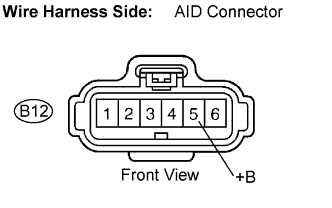
Disconnect the B12 Air Injection Control Driver (AID) connector.
-
Turn the ignition switch to the ON position.
-
Measure the voltage according to the value(s) in the table below.
Voltage Tester Connection Specified Condition +B (B12-5) - Body ground 9 to 14 V (near battery voltage) -
Reconnect the AID connector.
NG
REPAIR OR REPLACE HARNESS OR CONNECTOR
OK
-
-
CHECK HARNESS AND CONNECTOR (AIR INJECTION CONTROL DRIVER - BODY GROUND)
-
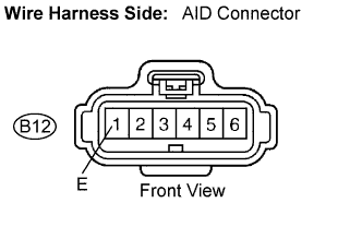
Disconnect the B12 AID connector.
-
Measure the resistance according to the value(s) in the table below.
Resistance Tester Connection Specified Condition E (B12-1) - Body ground Below 1 Ω -
Reconnect the AID connector.
NG
REPAIR OR REPLACE HARNESS OR CONNECTOR
OK
-
-
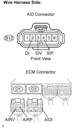
CHECK HARNESS AND CONNECTOR (AIR INJECTION CONTROL DRIVER - ECM)
-
Disconnect the B12 AID connector.
-
Disconnect the D1 and D3 ECM connectors.
-
Measure the resistance according to the value(s) in the table below.
Resistance Tester Connection Specified Condition DI (B12-2) - AIDI (D3-20) Below 1 Ω SIP (B12-4) - AIRP (D1-11) Below 1 Ω SIV (B12-3) - AIRV (D1-24) Below 1 Ω DI (B12-2) or AIDI (D3-20) - Body ground 10 kΩ or higher SIP (B12-4) or AIRP (D1-11) - Body ground 10 kΩ or higher SIV (B12-3) or AIRV (D1-24) - Body ground 10 kΩ or higher -
Connect the AID connector.
-
Connect the ECM connectors.
NG
REPAIR OR REPLACE HARNESS OR CONNECTOR
OK
-
-
INSPECT AIR INJECTION CONTROL DRIVER (DI TERMINAL VOLTAGE)
-
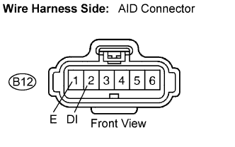
Disconnect the B12 AID connector.
-
Turn the ignition switch to the ON position.
-
Measure the voltage according to the value(s) in the table below.
Voltage Tester Connection Specified Condition DI (B12-2) - E (B12-1) 9 to 14 V (near battery voltage) -
Reconnect the AID connector.
NG 
CHECK HARNESS AND CONNECTOR (ECM - AIR INJECTION CONTROL DRIVER) Click here
OK 
REPLACE AIR INJECTION CONTROL DRIVER
-
-
CHECK HARNESS AND CONNECTOR (ECM - AIR INJECTION CONTROL DRIVER)
-
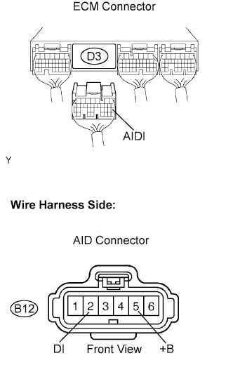
Disconnect the D3 ECM connector.
-
Disconnect the B12 AID connector.
-
Measure the resistance according to the value(s) in the table below.
Resistance (check for open) Tester Connection Specified Condition DI (B12-2) - AIDI (D3-20) Below 1 Ω Resistance (check for short) Tester Connection Specified Condition DI (B12-2) or AIDI (D3-20) -
+B (B12-5)
10 kΩ or higher -
Reconnect the ECM connector.
-
Reconnect the AID connector.
NG
REPAIR OR REPLACE HARNESS OR CONNECTOR
OK
REPLACE ECM
-