THROTTLE BODY INSTALLATION

-
INSTALL THROTTLE BODY ASSEMBLY
-
Install a new gasket onto the intake manifold.
Tech Tips
Align the protrusion of the gasket with the groove of the intake manifold.
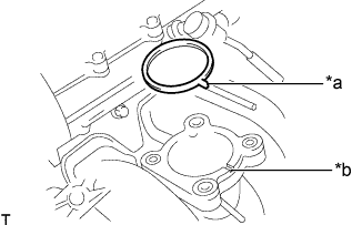
Text in Illustration *a Protrusion *b Groove -
Install the throttle body assembly with the 4 bolts.
- Torque:
- 9.0 N*m { 92 kgf*cm, 80 in.*lbf }
-
Connect the No. 2 water by-pass hose to the throttle body assembly, and slide the clamp to secure the hose.
-
Connect the water by-pass hose to the throttle body assembly, and slide the clamp to secure the hose.
-
Connect the throttle motor connector.
-
-
INSTALL INTAKE AIR CONNECTOR
-
Temporarily install the intake air connector to the throttle body assembly.
-
Connect the vacuum hose to the intake air connector.
-
Connect the No. 2 PCV hose to the cylinder head cover sub-assembly, and slide the clamp to secure the hose.
-
Install the intake air connector with the 2 bolts.
- Torque:
- 8.0 N*m { 82 kgf*cm, 71 in.*lbf }
-
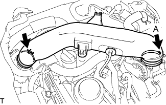
Tighten the 2 hose clamps.
- Torque:
- for clamp A
- 5.0 N*m { 51 kgf*cm, 44 in.*lbf }
-
-
ADD ENGINE COOLANT
-
Tighten the radiator drain cock plug by hand.
-
Tighten the cylinder block water drain cock plug.
- Torque:
- 13 N*m { 130 kgf*cm, 9 ft.*lbf }
-
Fill the radiator reservoir assembly with engine coolant to the top of the inlet.
Standard Capacity 11.2 liters (11.8 US qts, 9.9 Imp. qts) Note
Never use water as a substitute for engine coolant.
Tech Tips
TOYOTA vehicles are filled with TOYOTA SLLC at the factory. In order to avoid damage to the engine cooling system and other technical problems, only use TOYOTA SLLC or similar high quality ethylene glycol based non-silicate, non-amine, non-nitrite, non-borate coolant with long-life hybrid organic acid technology (coolant with long-life hybrid organic acid technology is a combination of low phosphates and organic acids).
-
Remove the 2-way that is located near the throttle body assembly.
-
When air is bleed and the engine coolant drains out, install the 2-way.
-
Add coolant through the radiator reservoir assembly filler opening until the coolant reaches the B line and install the radiator reservoir cap sub-assembly. [*1]
-
Warm up the engine until the thermostat opens. While the thermostat is open, circulate the coolant for several minutes. [*2]
CAUTION:
-
Wear protective gloves.
-
Be careful as the radiator hoses are hot.
-
Keep your hands away from the radiator fans.
Note
-
Immediately after starting the engine, if the radiator reservoir assembly does not have any engine coolant, perform the following: 1) stop the engine, 2) wait until the engine coolant has cooled down, and 3) add engine coolant.
-
Do not start the engine when there is no engine coolant in the radiator reservoir assembly.
-
Make sure that the needle does not show an abnormally high temperature.
-
If there is not enough engine coolant, the engine may overheat.
Tech Tips
-
Press the No. 2 and No. 3 radiator hoses several times by hand, and then check the level of the engine coolant.
-
The thermostat open timing can be confirmed by pressing the No. 3 radiator hose by hand, and checking when the engine coolant starts to flow inside the hose.
-
-
Stop the engine, and wait until the engine coolant cools down to ambient temperature. [*3]
-
Check the engine coolant level in the radiator reservoir assembly. [*4]
Tech Tips
-
If the engine coolant level is below the LOW line, repeat steps *1 through *4.
-
If the engine coolant level is above the FULL line, drain engine coolant until the engine coolant level is between the FULL and LOW line.
-
-
-
INSTALL ENGINE SERVICE HOLE SUB COVER SUB-ASSEMBLY
-
Install the engine service hole cover sub-assembly with the 5 bolts.
- Torque:
- 13 N*m { 133 kgf*cm, 10 ft.*lbf }
-
-
INSTALL FRONT DOOR SCUFF PLATE RH
-
INSTALL FRONT SEAT ASSEMBLY RH
-
CONNECT CABLE TO NEGATIVE BATTERY TERMINAL
Note
When disconnecting the cable, some systems need to be initialized after the cable is reconnected Click here.
-
PERFORM INITIALIZATION
Note
-
Be sure to perform this procedure after reassembling the throttle body assembly or removing and reinstalling any throttle body component.
-
Perform the following procedure after replacing the ECM, throttle body assembly or any throttle body components. The following procedure should also be performed if the throttle body is cleaned.
-
Be sure to perform this procedure after reconnecting the battery cable or replacing the ECM.
-
Disconnect the EFI No. 2 fuse and ETCS fuse at the same time. Wait at least 60 seconds and reconnect the fuses.
-
Turn the ignition switch to ON without operating the accelerator pedal.
Note
If the accelerator pedal is operated, perform the above steps again.
-
Connect the intelligent tester to the DLC3 and clear the DTCs Click here.
-
Start the engine and check that the MIL is not illuminated. After the engine is warmed up, check that the idle speed is within the specified range when the A/C is switched off.
Standard Condition Engine Idle Speed A/C switched off 650 to 750 rpm Note
-
Be sure to perform this step with all accessories off.
-
Make sure that the shift lever is in N or P.
-
-
Enter the following menus: Powertrain / Engine and ECT / Data List / All Data / Throttle Sensor Position. Fully depress the accelerator pedal and check that the value is 60% or more.
-
Perform a road test and confirm that there are no abnormalities.
-