FUEL SUPPLY PUMP INSTALLATION

Note
When replacing the fuel supply pump, common rail, cylinder block, cylinder head, cylinder head gasket or timing gear case, it is necessary to replace the fuel inlet pipe with a new one.
-
INSTALL FUEL SUPPLY PUMP ASSEMBLY
-
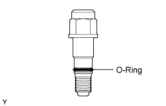
Install a new O-ring to the fuel supply pump.
-
Apply a light coat of engine oil to the O-ring.
-
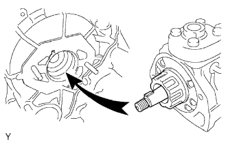
Align the groove of the injection gear with the set key on the drive shaft.
-
Install the fuel supply pump with the 2 nuts.
- Torque:
- 21 N*m { 214 kgf*cm, 15 ft.*lbf }
-
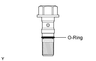
Install a new O-ring.
-
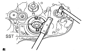
Using SST, hold the crankshaft pulley and install the set nut.
- SST
- 09213-58014
- 09330-00021
- Torque:
- 64 N*m { 650 kgf*cm, 47 ft.*lbf }
-
Install the pump drive shaft pulley and No. 2 camshaft timing pulley flange with the 4 bolts.
- Torque:
- 31 N*m { 316 kgf*cm, 23 ft.*lbf }
-
Connect the fuel temperature sensor connector and suction control valve connector.
-
w/ DPF:
Connect the fuel hose.
-
w/o DPF:
Connect the 2 fuel hoses.
-
-
INSTALL NO. 3 FUEL PIPE (w/ DPF)
-
Apply a light coat of fuel to the O-ring of the fuel check valve.
-
Temporarily install the No. 3 fuel pipe with the 3 bolts.
-
Temporarily install a new gasket and the fuel check valve.
-
Temporarily install 2 new gaskets and the 2 union bolts.
-
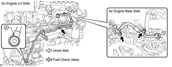
for Engine Rear Side:
Tighten the 2 bolts and union bolt.
- Torque:
- for union bolt
- 30 N*m { 306 kgf*cm, 22 ft.*lbf }
- for bolt
- 8.0 N*m { 82 kgf*cm, 71 in.*lbf }
-
for Engine LH Side:
-
Tighten the fuel check valve and bolt.
- Torque:
- for fuel check valve
- 32 N*m { 321 kgf*cm, 23 ft.*lbf }
- for bolt
- 8.0 N*m { 82 kgf*cm, 71 in.*lbf }
-
Using a 6 mm hexagon wrench, tighten the union bolt.
- Torque:
- 21 N*m { 214 kgf*cm, 15 ft.*lbf }
Note
Place the part of the gasket labeled A against the No. 3 fuel pipe as shown in the illustration and tighten the union bolt.
-
-
-
INSTALL NO. 2 EXHAUST MANIFOLD HEAT INSULATOR (w/ DPF)
-
Install the No. 2 exhaust manifold heat insulator with the 2 bolts.
- Torque:
- 13 N*m { 133 kgf*cm, 10 ft.*lbf }
-
-
INSTALL NO. 3 NOZZLE LEAKAGE PIPE (w/ DPF)
-
Apply a light coat of fuel to the O-ring of the fuel check valve.
-
Temporarily install the No. 3 nozzle leakage pipe with the bolt.
-
Temporarily install a new gasket and the fuel check valve.
-
Tighten the fuel check valve and bolt.
- Torque:
- for fuel check valve
- 32 N*m { 321 kgf*cm, 23 ft.*lbf }
- for bolt
- 13 N*m { 130 kgf*cm, 9 ft.*lbf }
-
Install the No. 2 injection pipe clamp with the bolt.
- Torque:
- 6.5 N*m { 66 kgf*cm, 58 in.*lbf }
-
Connect the 3 fuel hoses.
-
-
INSTALL FUEL INLET PIPE SUB-ASSEMBLY (w/o DPF)
Note
-
When replacing the fuel supply pump, common rail, cylinder block, cylinder head, cylinder head gasket or timing gear case, it is necessary to replace the fuel inlet pipe with a new one.
-
Keep the fuel inlet pipe free of foreign matter.
-
Temporarily install the fuel inlet pipe with the union nuts.
-
Install the No. 2 injection pipe clamp with the bolt.
- Torque:
- 5.0 N*m { 51 kgf*cm, 44 in.*lbf }
-
Install the No. 1 injection pipe clamp with the bolt.
- Torque:
- 5.0 N*m { 51 kgf*cm, 44 in.*lbf }
Note
If a No. 1 injection pipe clamp is removed from the fuel inlet pipe, replace the No. 1 injection pipe clamp with a new one.
-
Using a 17 mm union nut wrench, tighten the fuel inlet pipe union nut on the common rail side.
- Torque:
- 35 N*m { 357 kgf*cm, 26 ft.*lbf }
Note
Use the formula to calculate special torque values for situations where a union nut wrench is combined with a torque wrench Click here.
-
Using a 17 mm union nut wrench, tighten the fuel inlet pipe union nut on the fuel supply pump side.
- Torque:
- 35 N*m { 357 kgf*cm, 26 ft.*lbf }
Note
Use the formula to calculate special torque values for situations where a union nut wrench is combined with a torque wrench Click here.
-
-
INSTALL VANE PUMP ASSEMBLY
-
INSTALL EGR COOLER WITH NO. 2 EGR VALVE ASSEMBLY (w/ DPF)
-
INSTALL EGR COOLER ASSEMBLY (w/o DPF)
-
INSTALL TIMING BELT
-
CONNECT CABLE TO NEGATIVE BATTERY TERMINAL
-
BLEED AIR FROM FUEL SYSTEM
-
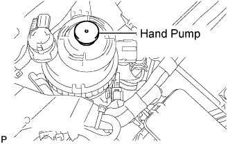
Using the hand pump mounted on the fuel filter cap, bleed air from the fuel system. Continue pumping until the pump resistance increases.
Note
-
Hand pump pumping speed: Max. 2 strokes/ sec.
-
The hand pump must be pushed with a full stroke during pumping.
-
When the fuel pressure at the supply pump inlet port reaches a saturated pressure, the hand pump resistance increases.
-
If pumping is interrupted during the air bleeding process, fuel in the fuel line may return to the fuel tank. Continue pumping until the hand pump resistance increases.
-
If the hand pump resistance does not increase despite consecutively pumping 200 times or more, there may be a fuel leak between the fuel tank and fuel filter, the hand pump may be malfunctioning, or the vehicle may have run out of fuel.
-
If air bleeding using the hand pump is incomplete, the common rail pressure does not rise to the pressure range necessary for normal use, and the engine cannot be started.
-
-
Check if the engine starts.
Note
-
Even if air bleeding using the hand pump has been completed, the starter may need to be cranked for 10 seconds or more to start the engine.
-
Do not crank the engine continuously for more than 20 seconds. The battery may be discharged.
-
Use a fully-charged battery.
-
When the engine can be started, proceed to the next step.
-
If the engine cannot be started, bleed air again using the hand pump until the hand pump resistance increases (refer to the procedures above). Then start the engine.
-
-
Turn the ignition switch off.
-
Connect the intelligent tester to the DLC3.
-
Turn the ignition switch to ON and turn the intelligent tester on.
-
Clear the DTCs.
-
w/ DPF: Click here
-
w/o DPF: Click here
-
-
Start the engine.*1
-
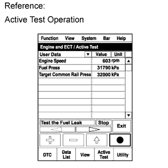
Enter the following menus: Powertrain / Engine and ECT / Active Test / Test the Fuel Leak.*2
-
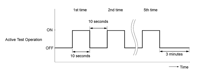
Perform the following test 5 times with on/off intervals of 10 seconds: Active Test / Test the Fuel Leak.*3
-
Allow the engine to idle for 3 minutes or more after performing the Active Test for the fifth time.
Tech Tips
When the Active Test "Test the Fuel Leak" is used to change the pump control mode, the actual fuel pressure inside the common rail drops below the target fuel pressure when the Active Test is off, but this is normal and does not indicate a pump malfunction.
-
Enter the following menus: Powertrain / Engine and ECT / DTC.
-
Read Current DTCs.
-
Clear the DTCs.
-
w/ DPF: Click here
-
w/o DPF: Click here
Tech Tips
It is necessary to clear the DTCs as DTC P1604 or P1605 may be stored when air is bled from the fuel system after replacing or repairing fuel system parts.
-
-
Repeat steps *1 to *3.
-
Enter the following menus: Powertrain / Engine and ECT / DTC.
-
Read Current DTCs.
OK No DTCs are output.
-
-
PERFORM FUEL SUPPLY PUMP INITIALIZATION
-
w/ DPF: Click here
-
w/o DPF: Click here
-
-
INSPECT FOR FUEL LEAK
-
Perform the Active Test.
-
Connect the intelligent tester to the DLC3.
-
Turn the ignition switch to ON.
-
Turn the intelligent tester on.
-
Enter the following menus: Powertrain / ECD / Active Test.
-
Perform the Active Test.
Intelligent Tester Display Test Part Control Range Diagnostic Notes Test the Fuel Leak Pressurize common rail interior and check for fuel leaks Stop/Start
-
Fuel pressure inside common rail increased to specified value and engine speed increased to 2000 rpm when Active Test is performed
-
Above conditions preserved while Active Test is being performed
-
-
-