FUEL INJECTOR (w/o DPF) REMOVAL

-
CHECK INJECTOR COMPENSATION CODE
-
Check that the injection compensation code registered in the injector assembly installed on each cylinder match the ones registered in the ECM Click here.
-
If they do not match, follow the procedures below to correct the registration details and recheck the symptom.
-
Correct the registration details by following the procedures in "resister injection compensation code" Click here.
-
After correcting the registration details, check if the same symptom occurs as when the vehicle was brought in.
Tech Tips
If it does not occur, the symptom may have been caused by errors in injection compensation code registration.
-
-
-
DISCONNECT CABLE FROM NEGATIVE BATTERY TERMINAL
-
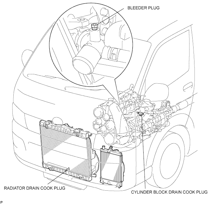
DRAIN ENGINE COOLANT
CAUTION:
Do not remove the radiator cap while the engine and radiator are still hot. Pressurized, hot engine coolant and steam may be released and cause serious burns.
-
Remove the radiator cap.
-
Loosen the radiator drain cock plug and a cylinder block drain cock plug. Then drain the coolant.
-
-
REMOVE FRONT SEAT ASSEMBLY RH
-

Move the front seat assembly fully forward.
-
Remove the 2 bolts on the rear side of the seat.
-
Move the front seat assembly to the rearmost position.
-
Remove the 2 bolts on the front side of the seat.
-
Move the front seat assembly to the center of the seat slide rail. Set the seatback in the upright position.
-
Disconnect the front seat inner belt assembly connector.
-
Remove the front seat assembly.
-
-
REMOVE FRONT DOOR SCUFF PLATE RH
-
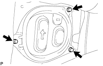
REMOVE ENGINE SERVICE HOLE SUB COVER SUB-ASSEMBLY
-
Roll up the carpet, and remove the 5 bolts and engine service hole sub cover sub-assembly.
-
-
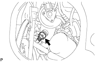
SEPARATE VANE PUMP OIL RESERVOIR ASSEMBLY
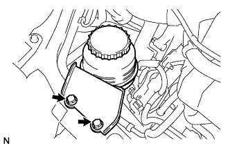
-
Remove the 2 bolts, and separate the vane pump oil reservoir assembly.
-
-
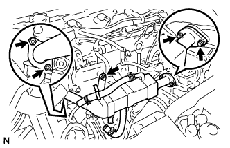
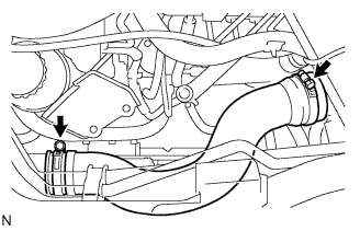
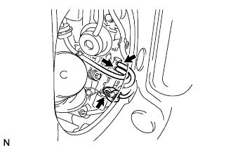
DISCONNECT OIL RETURN HOSE
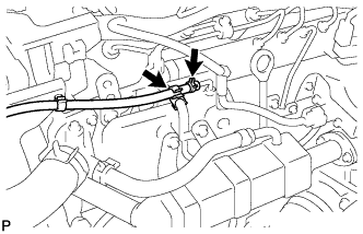
-
Loosen the 2 clips.
-
Disconnect the oil return hose.
-
-
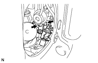
REMOVE EGR COOLER ASSEMBLY
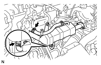
-
Loosen the clip and disconnect the No. 4 water by-pass hose.
-
Loosen the clip and disconnect the No. 2 water by-pass hose.
-
Remove the 3 bolts and 2 nuts and remove the EGR cooler assembly.
-
-
REMOVE NO. 4 AIR HOSE
-
Install the No. 4 air hose with the 2 clamps.
- Torque:
- 6.0 N*m { 61 kgf*cm, 53 in.*lbf }
-
-
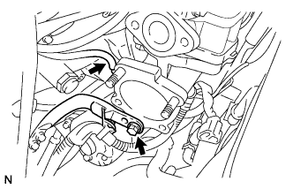
REMOVE DIESEL THROTTLE BODY ASSEMBLY
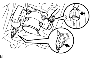
-
Disconnect the 2 throttle body connectors.
-
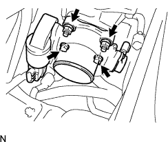
Remove the 2 bolts, 2 nuts and diesel throttle body assembly.
-
Remove the gasket from the intake air connector.
-
-
REMOVE NO. 2 ENGINE SERVICE HOLE COVER
-
Remove the 3 bolts and No. 2 engine service hole cover.
-
-
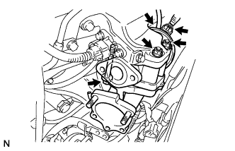
REMOVE ELECTRIC EGR CONTROL VALVE ASSEMBLY
-
Disconnect the intake air temperature sensor connector.
-
Remove the vacuum regulating valve.
-
Remove the 2 vacuum hoses and the vacuum regulating valve connector.
-
Remove the 2 bolts and the vacuum regulating valve.
-
-
Remove the electric EGR control valve with the sensor.
-
Remove the bolt, and separate the manifold stay.
-
Disconnect the vacuum hose from the intake air connector.
-
Disconnect the EGR valve position sensor connector.
-
Disconnect the vacuum hose from the electric EGR control valve.
-
Remove the bolt, 2 nuts and intake air connector assembly.
-
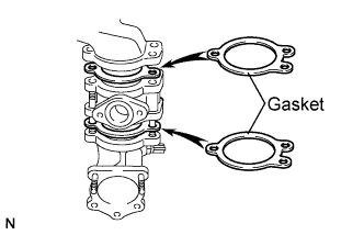
Remove the 2 gaskets and electric EGR control valve from the intake air connector.
-
-
-
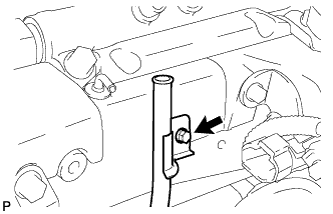
REMOVE OIL LEVEL GAUGE GUIDE
-
Remove the oil level gauge.
-
Remove the bolt and remove the oil level gauge guide.
-
-
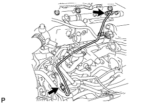
REMOVE INJECTION PIPE
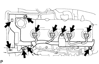
-
Disconnect the fuel injector connector and harness clamps.
-
Remove the 3 bolts.
-
Remove the 2 bolts and remove the 2 No. 2 injection pipe clamps.
-
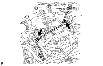
Using SST, remove the 4 injection pipes.
- SST
- 09023-12701
-
-
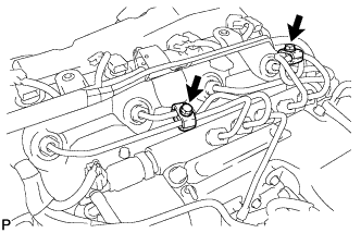
REMOVE FUEL INLET PIPE SUB-ASSEMBLY
-
Remove the 2 clamp bolts.
-
Using SST, loosen the 2 union nuts and remove the fuel inlet pipe sub-assembly.
- SST
- 09023-12701
-
-
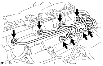
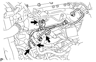
REMOVE NO. 2 NOZZLE LEAKAGE PIPE ASSEMBLY
-
Disconnect the 4 fuel hoses from the No. 2 nozzle leakage pipe assembly.
-
Remove the 2 union bolts, 3 bolts and remove the No. 2 nozzle leakage pipe assembly.
-
-
REMOVE CYLINDER HEAD COVER SUB-ASSEMBLY
-
Using a small screwdriver, remove the 4 holder seals by prying the portion between the holder seal and the cutout part of the cylinder head.
-
Disconnect the ventilation hose.
-
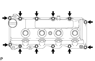
Remove the 10 bolts, 2 nuts, cylinder head cover and the cylinder head cover gasket.
-
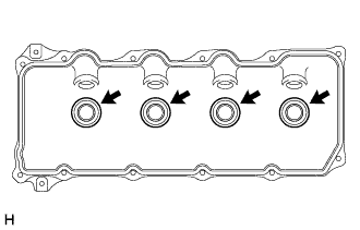
Remove the 4 No. 3 cylinder head cover gaskets from the cylinder head cover.
-
-
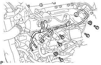
REMOVE INJECTOR ASSEMBLY
-
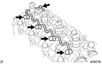
Remove the nozzle leakage pipe assembly.
-
Remove the union bolt, 4 hollow screws, 5 gaskets and nozzle leakage pipe assembly.
Note
Cover the plastic bag to prevent any foreign matter from entering the injector.
-
-
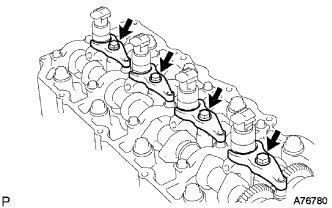
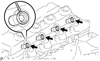
Remove the nozzle holder clamps.
-
Remove the 4 bolts, washers and 4 nozzle holder clamps.
Note
Be sure to keep the removed bolts, washers, and nozzle holder clamps separate for each cylinder.
-
-
Remove the injector assemblies.
-
Put tags with cylinder numbers (#1 to #4) on the removed injectors in order to match them into the correct cylinders.
-