FUEL INJECTOR (w/ DPF) REMOVAL

Note
-
When replacing the injectors (including shuffling the injectors between the cylinders), common rail or cylinder head, it is necessary to replace the injection pipes with new ones.
-
When replacing the fuel supply pump, common rail, cylinder block, cylinder head, cylinder head gasket or timing gear case, it is necessary to replace the fuel inlet pipe with a new one.
-
After removing the injection pipes, clean them with a brush and compressed air.
-
DISCHARGE REFRIGERANT FROM REFRIGERATION SYSTEM
-
Start up the engine.
-
Turn the A/C switch on.
-
Operate the cooler compressor at an engine rpm of approximately 1,000 for 5 to 6 minutes to circulate the refrigerant and collect compressor oil remaining in each component into the cooler compressor as much as possible.
-
Stop the engine.
-
Using SST, let the refrigerant gas out.
- SST
- 07110-58060 ( 07117-58080, 07117-58090, 07117-78050, 07117-88060, 07117-88070, 07117-88080 )
-
-
DISCONNECT CABLE FROM NEGATIVE BATTERY TERMINAL
-
CHECK INJECTOR COMPENSATION CODE
Tech Tips
If the injector compensation code is not correctly registered, it may cause malfunctions.
-
Read the injector compensation code Click here.
-
Check that the compensation code of the installed injector is the same as the code registered in the ECM. If the code is not as specified, register the injector compensation code of the injector Click here.
-
-
REMOVE EGR COOLER WITH NO. 2 EGR VALVE ASSEMBLY
-
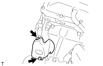
REMOVE COMPRESSOR ELBOW STAY
-
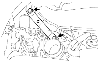
Remove the 2 bolts and compressor elbow stay.
-
-
REMOVE COMPRESSOR OUTLET ELBOW
-
Loosen the 2 hose clamps and remove the bolt and compressor outlet elbow.
-
-
REMOVE FAN AND GENERATOR V BELT
-
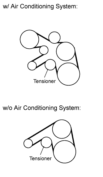
Remove the drive belt by rotating the tensioner pulley clockwise to loosen its tension with the pulley set bolt of the tensioner.
-
-
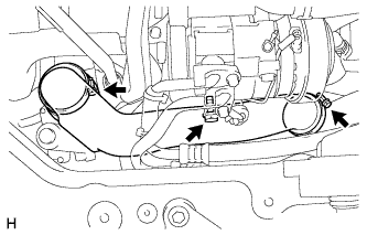
DISCONNECT NO. 1 COOLER REFRIGERANT DISCHARGE HOSE
-
Remove the bolt and disconnect the cooler refrigerant discharge hose from the compressor and magnetic clutch.
-
Remove the O-ring from the cooler refrigerant discharge hose.
Note
Seal the openings of the disconnected parts using vinyl tape to prevent moisture and foreign matter from entering.
-
-
DISCONNECT NO. 1 COOLER REFRIGERANT SUCTION HOSE
-
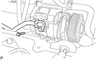
Remove the bolt and disconnect the cooler refrigerant suction hose.
-
Remove the O-ring from the cooler refrigerant suction hose.
Note
Seal the openings of the disconnected parts using vinyl tape to prevent moisture and foreign matter from entering.
-
-
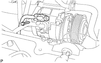
REMOVE COMPRESSOR AND MAGNETIC CLUTCH
-
Disconnect the connector.
-
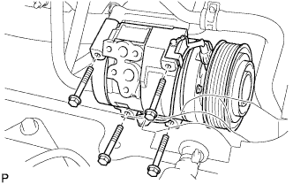
Remove the 4 bolts and compressor and magnetic clutch.
-
-
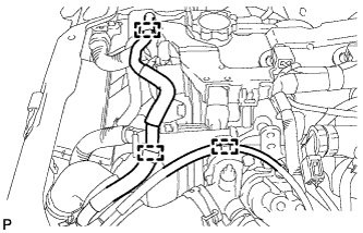
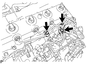
REMOVE NO. 3 NOZZLE LEAKAGE PIPE
-
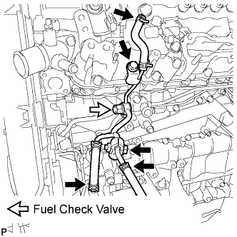
Disconnect the 3 fuel hoses.
-
Remove the bolt and No. 2 injection pipe clamp from the No. 3 nozzle leakage pipe and No. 3 fuel pipe.
-
Remove the fuel check valve and gasket.
-
Remove the bolt and No. 3 nozzle leakage pipe.
-
-
REMOVE NO. 2 EXHAUST MANIFOLD HEAT INSULATOR
-
Remove the 2 bolts and No. 2 exhaust manifold heat insulator.
-
-
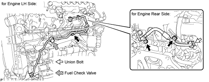
REMOVE NO. 3 FUEL PIPE
Tech Tips
It is not necessary to completely remove the No. 3 fuel pipe from the vehicle.
-
for Engine LH Side:
-
Using a 6 mm hexagon wrench, remove the union bolt and gasket.
-
Remove the fuel check valve and gasket.
-
Remove the bolt.
-
-
for Engine Rear Side:
-
Remove the union bolt and gasket.
-
Remove the 2 bolts.
-
-
-
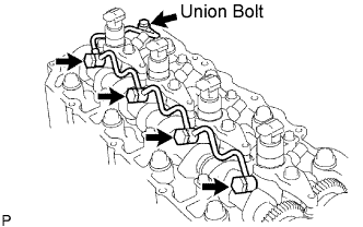
REMOVE NO. 2 NOZZLE LEAKAGE PIPE ASSEMBLY
-
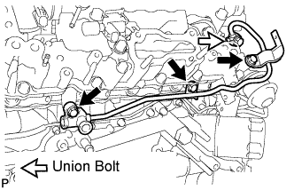
Remove the union bolt and gasket.
-
Remove the 3 bolts and No. 2 nozzle leakage pipe.
-
-
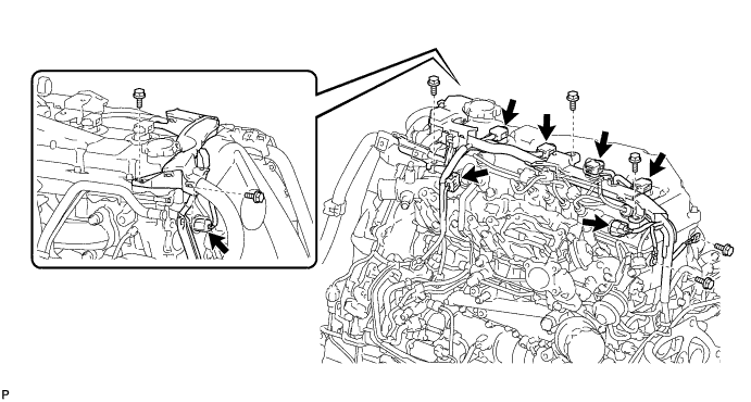
DISCONNECT ENGINE WIRE
-
Detach the 3 clamps and disconnect the water by-pass hose and oil return hose.
-
Detach the clamp and disconnect the glow plug connector.
-
Disconnect the 7 connectors.
-
Remove the 7 bolts and disconnect the engine wire.
-
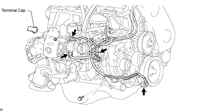
Disconnect the 4 connectors and detach the 3 clamps.
-
Remove the terminal cap.
-
Remove the nut and disconnect the wire harness from terminal B.
-
Remove the bolt and disconnect the engine wire.
-
Fold back the floor carpet.
-
Disconnect the 6 ECM connectors.
-
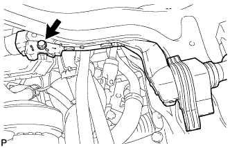
Remove the bolt.
-
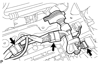
Disconnect the 3 connectors.
-
-
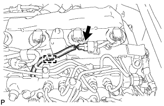
REMOVE INJECTION PIPE SUB-ASSEMBLY
-
Remove the 3 bolts and 3 No. 2 injection pipe clamps.
-
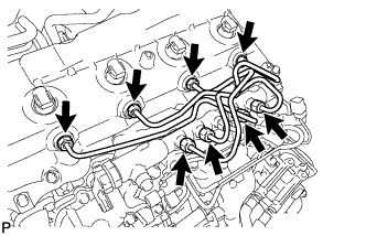
Using a 17 mm union nut wrench, loosen the union nuts and remove the 4 injection pipes.
-
-
REMOVE COMMON RAIL ASSEMBLY
-
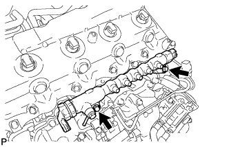
Remove the 2 bolts and common rail.
Note
Do not remove the pressure discharge valve or fuel pressure sensor.
-
-
REMOVE NO. 1 INTAKE MANIFOLD INSULATOR
-
REMOVE NO. 1 CYLINDER HEAD COVER SILENCER
-
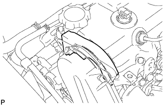
Remove the No. 1 cylinder head cover silencer from the cylinder head cover.
-
-
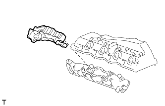
REMOVE CYLINDER HEAD COVER SUB-ASSEMBLY
-
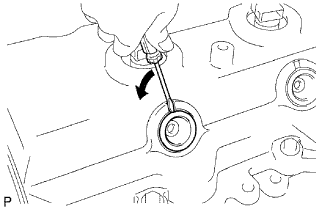
Using a small screwdriver, remove the nozzle holder seal by prying between the nozzle holder seal and the cutout part of the cylinder head cover.
-
Disconnect the ventilation hose.
-
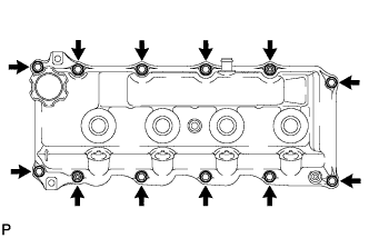
Remove the 10 bolts, 2 nuts, cylinder head cover and the cylinder head cover gasket.
-
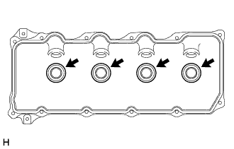
Remove the 4 No. 3 cylinder head cover gaskets from the cylinder head cover.
-
-
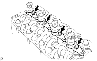
REMOVE INJECTOR ASSEMBLY
-
Remove the union bolt, 4 injector hollow screws, 5 gaskets and nozzle leakage pipe.
Note
-
When removing the nozzle leakage pipe, place a cushion under the pipe.
-
Be careful not to deform or scratch the union seal surface.
-
After removing the fuel pipe, put it in a plastic bag to prevent foreign matter from contaminating its injector inlet.
-
-
Remove the 4 bolts, 4 washers, 4 No. 1 nozzle holder clamps and 4 injectors.
Tech Tips
Arrange the injectors, No. 1 nozzle holder clamps, washers and bolts in the correct order.
-
Remove the O-ring from each injector.
-
Remove the 4 injection nozzle seats from the cylinder head.
-