COMMON RAIL (w/ DPF) REMOVAL

Note
-
When replacing the injectors (including shuffling the injectors between the cylinders), common rail or cylinder head, it is necessary to replace the injection pipes with new ones.
-
When replacing the fuel supply pump, common rail, cylinder block, cylinder head, cylinder head gasket or timing gear case, it is necessary to replace the fuel inlet pipe with a new one.
-
After removing the injection pipes and fuel inlet pipe, clean them with a brush and compressed air.
-
DISCHARGE REFRIGERANT FROM REFRIGERATION SYSTEM
-
Start up the engine.
-
Turn the A/C switch on.
-
Operate the cooler compressor at an engine rpm of approximately 1,000 for 5 to 6 minutes to circulate the refrigerant and collect compressor oil remaining in each component into the cooler compressor as much as possible.
-
Stop the engine.
-
Using SST, let the refrigerant gas out.
- SST
- 07110-58060 ( 07117-58080, 07117-58090, 07117-78050, 07117-88060, 07117-88070, 07117-88080 )
-
-
DRAIN ENGINE COOLANT
-
DISCONNECT CABLE FROM NEGATIVE BATTERY TERMINAL
-
REMOVE DIESEL THROTTLE BODY ASSEMBLY
-
REMOVE FRONT DOOR SCUFF PLATE RH
-
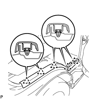
Detach the 5 clips and remove the front door scuff plate RH.
-
-
REMOVE FRONT SEAT ASSEMBLY RH
-
REMOVE ENGINE SERVICE HOLE SUB COVER SUB-ASSEMBLY
-
Roll up the carpet and remove the engine service hole sub cover.
-
-
REMOVE COMPRESSOR OUTLET ELBOW
-
Loosen the 2 hose clamps and remove the bolt and compressor outlet elbow.
-
-
REMOVE FAN AND GENERATOR V BELT
-
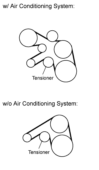
Remove the drive belt by rotating the tensioner pulley clockwise to loosen its tension with the pulley set bolt of the tensioner.
-
-
DISCONNECT NO. 1 COOLER REFRIGERANT DISCHARGE HOSE
-
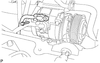
Remove the bolt and disconnect the cooler refrigerant discharge hose from the compressor and magnetic clutch.
-
Remove the O-ring from the cooler refrigerant discharge hose.
Note
Seal the openings of the disconnected parts using vinyl tape to prevent moisture and foreign matter from entering.
-
-
DISCONNECT NO. 1 COOLER REFRIGERANT SUCTION HOSE
-
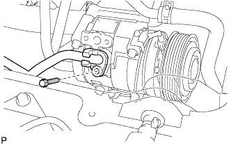
Remove the bolt and disconnect the cooler refrigerant suction hose.
-
Remove the O-ring from the cooler refrigerant suction hose.
Note
Seal the openings of the disconnected parts using vinyl tape to prevent moisture and foreign matter from entering.
-
-
REMOVE COMPRESSOR AND MAGNETIC CLUTCH
-
Disconnect the connector.
-
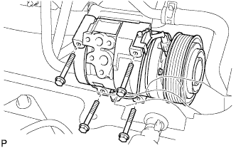
Remove the 4 bolts and compressor and magnetic clutch.
-
-
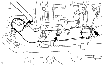
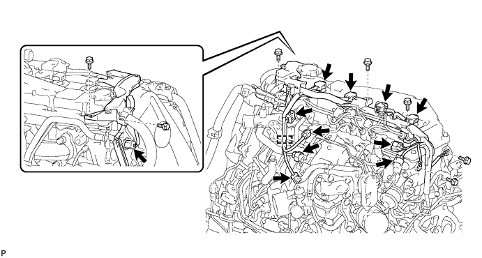
DISCONNECT ENGINE WIRE
-
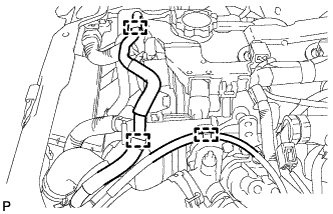
Detach the 3 clamps and disconnect the water by-pass hose and oil return hose.
-
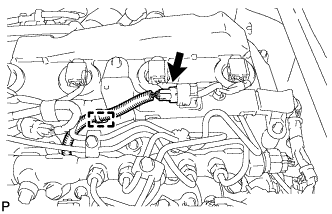
Detach the clamp and disconnect the glow plug connector.
-
Detach the clamp and disconnect the engine wire from the No. 1 timing belt cover.
-
Disconnect the 11 connectors and detach the clamp.
-
Remove the 7 bolts and disconnect the engine wire.
-
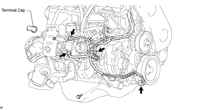
Disconnect the 4 connectors and detach the 3 clamps.
-
Remove the terminal cap.
-
Remove the nut and disconnect the wire harness from terminal B.
-
Remove the bolt and disconnect the engine wire.
-
Fold back the floor carpet.
-
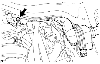
Remove the bolt.
-
Detach the clamp.
-
Disconnect the ECM connector Click here.
-
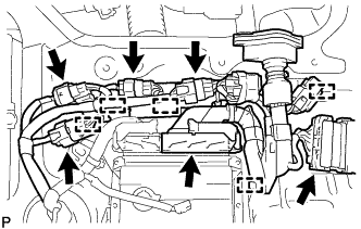
Disconnect the 5 connectors.
-
Detach the 5 clamps.
-
-
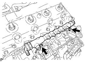
REMOVE INJECTION PIPE SUB-ASSEMBLY
-
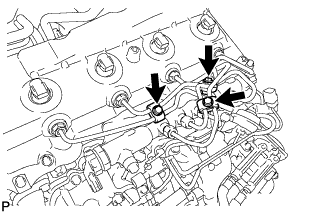
Remove the 3 bolts and 3 No. 2 injection pipe clamps.
-
Using a 17 mm union nut wrench, loosen the union nuts and remove the 4 injection pipes.
-
-
REMOVE VACUUM CONTROL VALVE SET
-
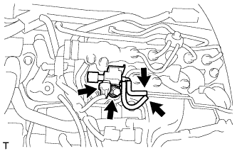
Disconnect the vacuum control valve connector and 2 vacuum hoses from the No. 3 vacuum transmitting pipe sub-assembly.
-
Remove the bolt and vacuum control valve set.
-
-
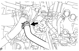
DISCONNECT NO. 5 WATER BY-PASS HOSE
-
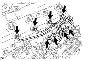
REMOVE FUEL INLET PIPE SUB-ASSEMBLY
Note
If a No. 1 injection pipe clamp is removed from the fuel inlet pipe, replace the No. 1 injection pipe clamp with a new one.
-
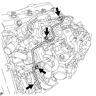
Remove the 2 bolts and 2 No. 1 injection pipe clamps.
-
Using a 17 mm union nut wrench, loosen the union nuts and remove the fuel inlet pipe.
-
-
REMOVE COMMON RAIL ASSEMBLY
-
Remove the 2 bolts and common rail.
Note
Do not remove the pressure discharge valve or fuel pressure sensor.
-