TILT CAB TUBE INSTALLATION

-
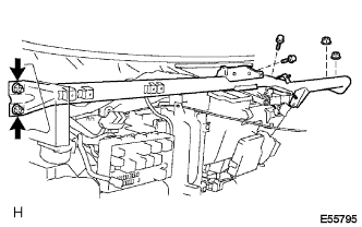
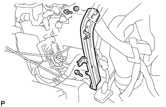
INSTALL TILT CAB TUBE SUB-ASSEMBLY NO.1
-
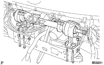
Install the tilt cab tube sub-assembly No. 1 with 6 bolts and 6 nuts.
- Torque:
- 185 N*m { 1,880 kgf*cm, 136.4 ft.*lbf }
-
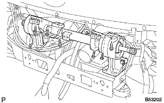
Install the 6 bolts.
- Torque:
- 58 N*m { 590 kgf*cm, 42.7 ft.*lbf }
-
-
CAB TILT UP
-
INSTALL TILT CAB SPRING SUPPORT ARM NO.1
-
Align matchmarks tilt cab spring support arm No. 1 on torsion-bar.
-
Install the tilt cab spring support arm No. 1 with bolt.
- Torque:
- 58 N*m { 590 kgf*cm, 42.7 ft.*lbf }
-
-
INSTALL REAR BRAKE TUBE NO.1
-
Install the retainer.
-
Using union nut wrench 10 mm, install the rear brake tube No. 1.
- Torque:
- 15.2 N*m { 155 kgf*cm, 11.2 ft.*lbf }
-
-
INSTALL FRONT BRAKE TUBE NO.1
-
Install the retainer.
-
Using union nut wrench 10 mm, install the front brake tube No. 1.
- Torque:
- 15.2 N*m { 155 kgf*cm, 11.2 ft.*lbf }
-
-
INSTALL CLUTCH MASTER CYLINDER TO FLEXIBLE HOSE TUBE
-
Install the retainer.
-
Using union nut wrench 10 mm, install the clutch hose.
- Torque:
- 19.5 N*m { 190 kgf*cm, 14.3 ft.*lbf }
-
-
INSTALL RADIATOR GRILLE BRACKET NO.2
-
Install the radiator grille bracket with bolt.
- Torque:
- 8.5 N*m { 85 kgf*cm, 75 in.*lbf }
-
-
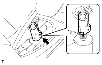
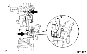
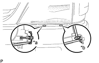
INSTALL STEERING SLIDING W/COUPLING YOKE SUB-ASSEMBLY (INDEPENDENT FRONT SUSPENSION FRONT SUSPENSION)
-
Align the matchmarks on the steering sliding w/coupling yoke and the bevel gear assembly.
Text in Illustration *a Matchmark -
Install the bolt.
- Torque:
- 35 N*m { 357 kgf*cm, 26 ft.*lbf }
-
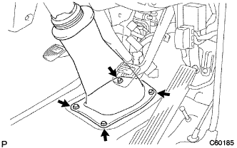
Install the steering column tube lower with the 4 bolts.
- Torque:
- 8.0 N*m { 82 kgf*cm, 71 in.*lbf }
-
-
INSTALL STEERING MAIN SHAFT ASSEMBLY
-
INSTALL FRONT BUMPER BAR
-
Install the front bumper bar with the 6 bolts.
- Torque:
- 18 N*m { 185 kgf*cm, 13 ft.*lbf }
-
Connect the fog light connectors.
-
-
INSTALL AIRMIX DAMPER CONTROL CABLE SUB-ASSEMBLY
-
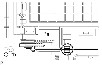
Text in Illustration *a COOL *b Clamp Connect the heater control cable to the heater control assembly, keep the condition of MAX COOL remaining.
-
Install the inner cable to the control lever in MAX COOL position.
-
Install the outer cable to the clamp while slightly pulling it to the direction shown by arrow in the illustration.
Note
When operating the mode control lever, check that the restraint exists at the both ends of MAX COOL and MAX HOT, and no repulsion occurs.
-
-
INSTALL HEATER CONTROL CABLE SUB-ASSEMBLY
-
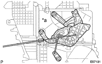
Text in Illustration *a DEF Connect the heater control cable to the heater control assembly, keep the condition of DEF remaining.
-
Install the inner cable to the control lever in DEF position.
-
Install the outer cable to the clamp while slightly pulling it to the direction shown by arrow in the illustration.
Note
When operating the mode control lever, check that the restraint exists at the both ends of FACE and DEF, and no repulsion occurs.
-
-
INSTALL HEATER RADIATOR ASSEMBLY
-
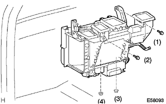
Install the heater radiator assembly with the 2 bolts and 2 nuts.
Tech Tips
Tighten in the following order.
-
-
INSTALL AIR DUCT SUB-ASSEMBLY NO.1
-
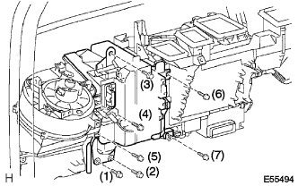
Install the air duct sub-assembly No. 1 with the 3 bolts and 4 screws.
Tech Tips
Tighten in the following order.
-
-
INSTALL INSTRUMENT PANEL REINFORCEMENT
-
Install the instrument panel reinforcement with the 2 bolts and 4 nuts.
-
-
INSTALL STEERING COLUMN TUBE ASSEMBLY LOWER
-
Install the steering column tube sub-assembly lower with the 2 bolts and 2 nuts.
-
-
INSPECT INSTRUMENT PANEL PASSENGER AIR BAG ASSEMBLY
-
INSTALL INSTRUMENT PANEL PASSENGER AIR BAG ASSEMBLY
-
INSTALL COMBINATION METER ASSEMBLY
-
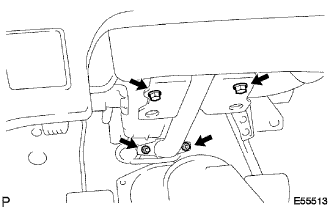
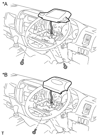
INSTALL STEERING COLUMN ASSEMBLY
-
Install the 4 bolts and steering column assembly.
Text in Illustration *A Non-Tilt Steering Column *B Tilt Steering Column - Torque:
- 11.5 N*m { 117 kgf*cm, 9 ft.*lbf }
-
Install the 2 bolts and clamp bracket.
-
-
INSTALL STEERING COLUMN COVER LWR
-
Install the steering column cover LWR with the clip and 2 screws.
-
-
INSTALL STEERING COLUMN COVER UPR
-
Install the steering column cover UPR with the 2 screws.
-
-
INSTALL INSTRUMENT PANEL BRACE SUB-ASSEMBLY NO.1
-
Install the instrument panel brace sub-assembly with the 2 bolts and nut.
-
-
INSTALL INSTRUMENT PANEL SUB-ASSEMBLY
-
ADD COOLANT
-
INSPECT ENGINE COOLANT LEAK
-
WARM UP ENGINE
-
INSTALL TURN SIGNAL SWITCH ASSEMBLY
-
PLACE FRONT WHEELS FACING STRAIGHT AHEAD
-
INSPECT STEERING WHEEL ASSEMBLY
-
INSPECT HORN BUTTON ASSEMBLY (W/ SRS AIRBAG)
-
CENTER SPIRAL CABLE
-
INSTALL STEERING WHEEL ASSEMBLY
-
Align the matchmarks on the steering wheel assembly with the one on the steering main shaft.
-
Install the steering wheel set nut.
- Torque:
- 50 N*m { 510 kgf*cm, 37 ft.*lbf }
-
-
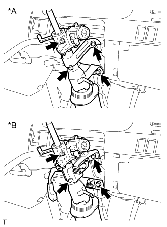
INSTALL HORN BUTTON ASSEMBLY (W/O SRS AIRBAG)
Text in Illustration *A Non-Tilt Steering Column *B Tilt Steering Column
-
Non-Tilt Steering Column:
-
Connect the horn button connector.
-
Install the 2 screws and horn button assembly.
-
-
Tilt Column Steering:
-
Connect the horn button connector.
-
Install the bolt and horn button assembly.
- Torque:
- 2.0 N*m { 20 kgf*cm, 18 in.*lbf }
-
-
-
INSTALL HORN BUTTON ASSEMBLY (W/ SRS AIRBAG)
-
BLEED BRAKE LINE
-
CHECK BRAKE FLUID LEAKAGE
-
CHECK FLUID LEVEL IN RESERVOIR
-
BLEED CLUTCH PIPE LINE
-
CHECK CLUTCH FLUID LEAKAGE
-
INSPECT SRS WARNING LIGHT
-
HEADLIGHT AIM ONLY
-
Place the vehicle in the following conditions.
-
The vehicle is parked on a level surface.
-
Tire inflation pressure is the specified value.
-
A driver is in the driver's seat and the vehicle is in a state ready for driving (with a tank full).
-
The vehicle has been bounced several times.
-
-
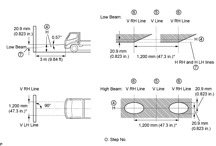
Check the headlight aiming.
-
Prepare a thick white paper.
-
Stand the paper perpendicular to the ground at the position 9.84 ft away from the headlights.
-
Ensure that the center line of the vehicle and the paper face forms a 90-degree angle as shown in the illustration.
-
Draw a horizontal line (H line) on the paper, showing where the headlights should strike.
-
Draw a vertical line (V line) to where the center line of the vehicle is to be.
-
Draw 2 vertical lines to where the both headlights should strike (V RH and V LH lines).
-
Draw a horizontal line (by connecting the both low beam center marks) to where the headlights should strike (H RH and H LH lines).
Tech Tips
The H RH and H LH line is 0.57° below the horizontal line (H line) of the light axis.
-
Start the engine.
-
Turn the headlights ON.
-
Check that the headlights properly strike the position shown in the illustration.
-
If not, adjust the lights in the vertical or horizontal direction.
Tech Tips
-
As shown in the illustration, adjust each aim of the RH and LH lights.
-
Since the horizontal direction is impossible to adjust, the value * of the "Low Beam" aim is reference value.
-
-
-
Text in Illustration *a Bolt A *b Bolt B When adjusting it in the vertical direction: Using adjusting bolt A, adjust the headlight aim to within the specified range.
-
When adjusting it in the horizontal direction: Using adjusting bolt B, adjust the headlight aim to within the specified range.
-