TILT CAB TUBE REMOVAL

-
PRECAUTION
-
SEPARATE BATTERY NEGATIVE TERMINAL
-
PLACE FRONT WHEELS FACING STRAIGHT AHEAD
-
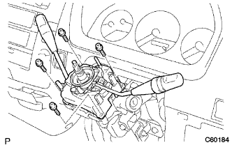
REMOVE HORN BUTTON ASSEMBLY (W/O SRS AIRBAG)
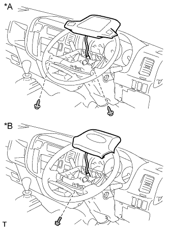
Text in Illustration *A Non-Tilt Column Assembly *B Tilt Column Assembly
-
Non-Tilt Column Assembly:
-
Remove the 2 screws and horn button assembly.
-
Disconnect the horn button connector.
-
-
Tilt Column Assembly:
-
Remove the screw and horn button assembly.
-
Disconnect the horn button connector.
-
-
-
REMOVE HORN BUTTON ASSEMBLY (W/ SRS AIRBAG)
-
REMOVE STEERING WHEEL ASSEMBLY
-
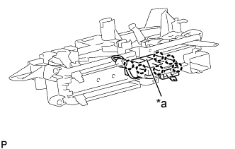
Remove the steering wheel assembly set nut.
-
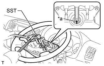
Text in Illustration *a Matchmark Place matchmarks on the steering wheel assembly and main shaft assembly.
-
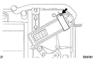
Using SST, remove the steering wheel assembly.
- SST
- 09950-50013 ( 09951-05010, 09952-05010, 09953-05010, 09954-05021 )
-
-
REMOVE STEERING COLUMN COVER UPR
-
Remove the 2 screws and steering column cover UPR.
-
-
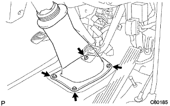
REMOVE STEERING COLUMN COVER LWR
-
Remove the clip, 2 screws and steering column cover LWR.
-
-
REMOVE TURN SIGNAL SWITCH ASSEMBLY
-
Disconnect the connectors and wire harness clamps.
-
Remove the 4 screws and turn signal switch assembly.
-
-
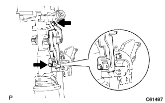
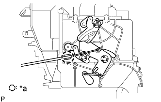
SEPARATE STEERING MAIN SHAFT ASSEMBLY (RIGID FRONT SUSPENSION)
-
Remove the 4 bolts.
-
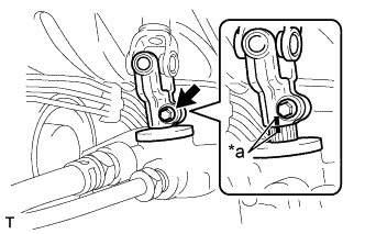
Text in Illustration *a Matchmark Place matchmarks on the steering main shaft assembly and power steering gear assembly after lifting steering main shaft.
-
-
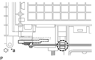
SEPARATE STEERING SLIDING W/COUPLING YOKE SUB-ASSEMBLY (INDEPENDENT FRONT SUSPENSION)
-
Remove the 4 bolts.
-
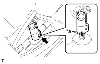
Text in Illustration *a Matchmark Place matchmarks on the steering sliding w/coupling yoke sub-assembly and bevel gear assembly after lifting steering sliding w/coupling yoke sub-assembly.
-
-
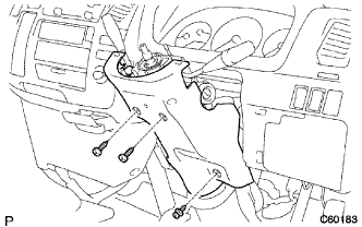
REMOVE STEERING COLUMN ASSEMBLY
-
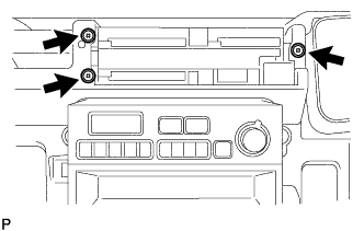
Remove the 2 bolts and clamp bracket.
-
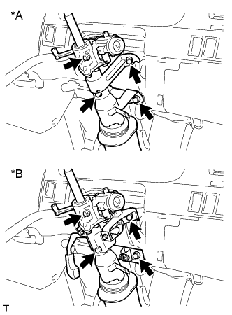
Text in Illustration *A Non-Tilt Column Assembly *B Tilt Column Assembly Remove the 4 steering column assembly set bolts and steering column assembly.
-
-
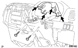
REMOVE INSTRUMENT CLUSTER FINISH PANEL SUB-ASSEMBLY CENTER
-
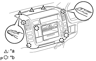
Text in Illustration *a 3 Clips *b 6 Claws Disengage the 3 clips and 6 claws.
-
Disconnect the connectors and remove the instrument cluster finish panel sub-assembly center.
-
-
REMOVE HEATER CONTROL LEVER KNOB (W/ HEATER)
-
Remove the 4 heater control lever knobs.
-
-
REMOVE HEATER CONTROL NAME PLATE (W/ HEATER)
-
Text in Illustration *a 4 Claws Release the 4 claw fittings, remove the heater control name plate.
-
-
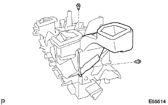
REMOVE HEATER OR BOOST VENTILATOR CONTROL ASSEMBLY
-
Spread the clamp's claws of the defroster damper control cable and disconnect the inner cable.
-
Spread the clamp's claws of the air inlet damper control cable and disconnect the inner cable.
-
Text in Illustration *a Claw Release the claw fitting, remove the heater blower switch assembly and bulb.
-
Remove the 3 screws and heater or boost ventilator control assembly.
-
Spread the clamp's claws of the air mix damper control cable and disconnect the inner cable.
-
Disconnect the connector, remove the heater or boost ventilator control assembly.
-
-
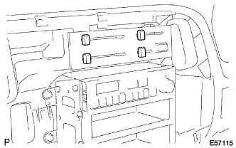
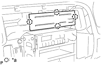
REMOVE RADIO BRACKET NO.1&NO.2
-
Remove the 4 screws and radio bracket No. 1.
-
-
REMOVE GLOVE COMPARTMENT DOOR ASSEMBLY
-
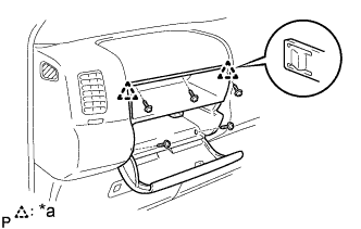
Text in Illustration *a 2 Claws Remove the 5 screws<D>.
-
Disengage the 2 claws and remove the glove compartment door assembly.
-
-
REMOVE INSTRUMENT COVER LWR (W/O HEATER)
-
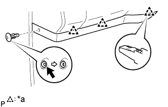
Text in Illustration *a 3 Clips Disengage the 3 clips and remove the instrument cover LWR.
-
-
REMOVE INSTRUMENT COVER LWR (W/ HEATER)
-
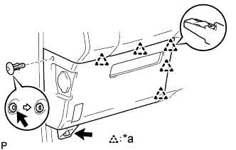
Text in Illustration *a 5 Clips Remove the clip and bolt.
-
Disengage the 5 clips and remove the instrument cover LWR.
-
-
REMOVE INSTRUMENT COVER LOWER CENTER (W/ HEATER)
-
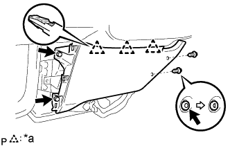
Text in Illustration *a 3 Clips Remove the 2 clips and 2 bolts.
-
Disengage the 3 clips and remove the instrument cover lower center.
-
-
REMOVE INSTRUMENT CLUSTER FINISH PANEL CENTER
-
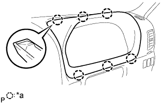
Text in Illustration *a 6 Claws Using a moulding remover, disengage the 6 claws and remove the instrument cluster finish panel.
-
-
REMOVE COMBINATION METER ASSEMBLY
-
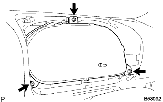
Remove the 3 screws.
-
Disconnect the connectors and remove the combination meter assembly.
-
-
REMOVE THROTTLE CONTROL CABLE KNOB (5L ENGINE TYPE)
-
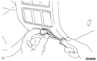
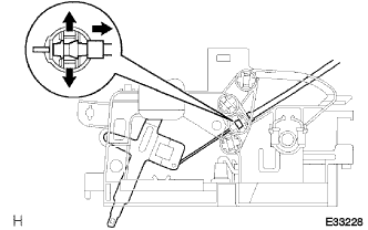
Using a screwdriver, put the claw for accel control w/ throttle cable assembly and remove the throttle control cable knob.
Tech Tips
Tape the screwdriver tip, before use.
-
-
REMOVE ACCEL CONTROL W/THROTTLE CABLE ASSEMBLY (5L ENGINE TYPE)
-
Remove the nut and accel control w/ throttle cable assembly.
-
-
REMOVE OIL RESERVOIR TANK COVER RH (RHD STEERING POSITION TYPE)
-
REMOVE OIL RESERVOIR TANK COVER LH (LHD STEERING POSITION TYPE)
-
REMOVE INSTRUMENT PANEL SUB-ASSEMBLY
-
Remove the 2 clips.
-
Remove the 2 nuts<F> and 7 bolts<A><B>.
-
Disconnect the connectors and remove the instrument panel sub-assembly.
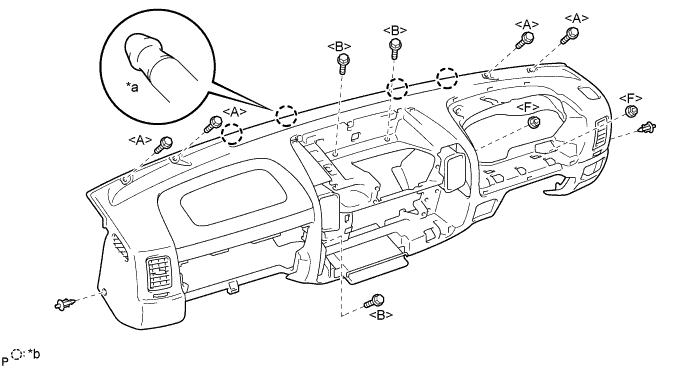
Text in Illustration *a Pin *b 4 Pins
-
-
REMOVE RADIATOR GRILLE
-
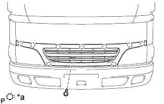
Text in Illustration *a Clip Remove the screw and 9 clips and radiator grille.
-
-
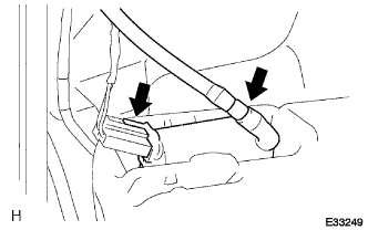
SEPARATE HEATER WATER INLET HOSE B
-
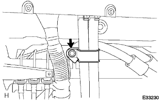
Remove the bolt and heater water bracket.
-
Slide the clip and disconnect the heater water inlet hose B.
-
-
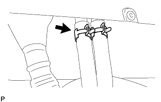
SEPARATE HEATER WATER OUTLET HOSE B
-
Slide the clip and disconnect the heater water outlet hose B.
-
-
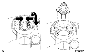
SEPARATE BRAKE MASTER CYLINDER RESERVOIR SUB-ASSEMBLY
-
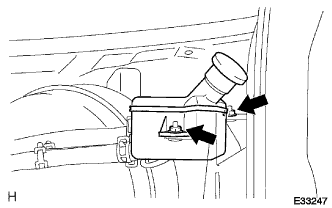
Remove the 2 nuts and disconnect bracket master cylinder reservoir sub-assembly.
-
-
REMOVE INSTRUMENT PANEL BRACE SUB-ASSEMBLY NO.1
-
Remove the 2 bolts, nut and instrument panel brace sub- assembly No. 1.
-
-
REMOVE FRONT DOOR SCUFF PLATE RH
-
Remove the 4 screws and front door scuff plate RH.
-
-
REMOVE AIR DUCT NO.2 (LHD STEERING POSITION TYPE)
-
REMOVE AIR DUCT NO.1
-
REMOVE INSTRUMENT PANEL REINFORCEMENT
-
Remove the 2 bolts, 4 nuts and instrument panel reinforcement.
-
-
REMOVE WINDSHIELD WASHER JAR ASSEMBLY
-
Remove the 2 bolts and windshield washer jar.
-
Disconnect the hose and connector from washer pump.
-
-
REMOVE AIR DUCT SUB-ASSEMBLY NO.1
-
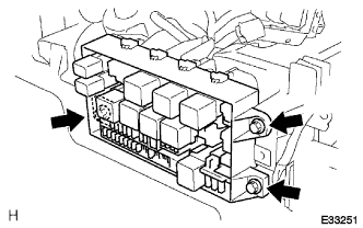
Remove the 3 bolts and disconnect the relay block assembly.
-
Remove the screw and disconnect the relay block assembly.
-
Remove the bolt.
-
Disconnect the blower resistor connector.
-
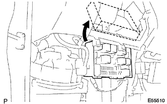
Disconnect the relay block assembly.
-
Remove the 2 bolts, 4 screws and air duct sub-assembly No. 1.
-
-
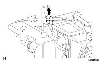
REMOVE DEFROSTER NOZZLE ASSEMBLY LOWER
-
Remove the screw and defroster nozzle assembly LWR.
-
-
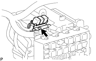
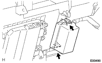
SEPARATE SKID CONTROL ECU ASSEMBLY
-
Remove the 2 screws and disconnect the skid control ECU assembly.
-
-
SEPARATE PREHEATING TIMER (5L ENGINE TYPE)
-
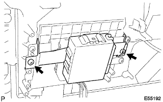
SEPARATE ECM (2KD-FTV ENGINE TYPE)
-
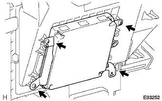
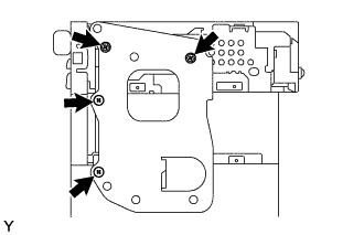
Remove the 4 screws and disconnect the ECM.
-
-
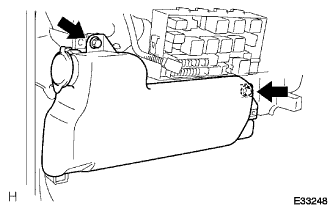
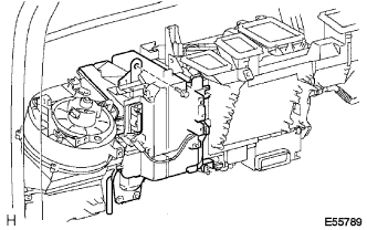
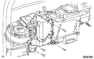
REMOVE HEATER RADIATOR ASSEMBLY
-
Release the 2 claws, disconnect the connector.
-
Disconnect the outer cable from the clamp.
-
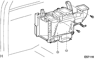
Remove the 2 bolts, 2 nuts and heater radiator assembly.
-
-
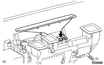
REMOVE HEATER TO REGISTER DUCT NO.2
-
Remove the 2 clips and heater to register duct No. 2.
-
-
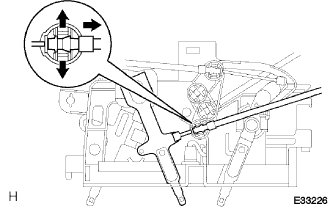
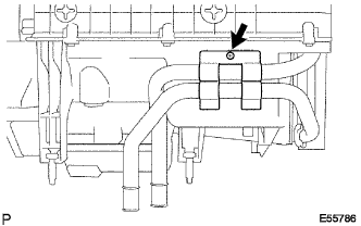
SEPARATE HEATER CONTROL CABLE SUB-ASSEMBLY
-
Text in Illustration *a Clamp Disconnect the outer cable from the clamp.
-
Remove the inner cable.
-
-
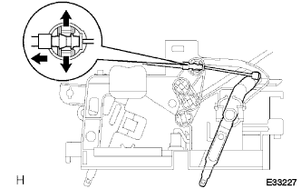
REMOVE AIRMIX DAMPER CONTROL CABLE SUB-ASSEMBLY
-
Text in Illustration *a Clamp Disconnect the outer cable from the clamp.
-
Remove the inner cable.
-
-
REMOVE HEATER RADIATOR UNIT SUB-ASSEMBLY
-
Remove the screw and bracket.
-
Remove the screw, bracket and heater radiator unit sub- assembly.
-
-
REMOVE FRONT BUMPER BAR
-
Disconnect the fog light connectors.
-
Remove the 6 bolts and front bumper bar.
-
-
REMOVE CLEARANCE LAMP LENS & BODY LH
-
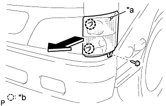
Text in Illustration *a Pin *b Claw Remove the screw.
-
Pull out the clearance light lens & body LH forward, then disconnect the pin of body side.
-
Disconnect the connectors.
-
-
REMOVE CLEARANCE LAMP LENS & BODY RH
-
Text in Illustration *a Pin *b Claw Remove the screw.
-
Pull out the clearance light lens & body LH forward, then disconnect the pin of body side.
-
Disconnect the connectors.
-
-
REMOVE HEADLAMP UNIT ASSEMBLY LH
-
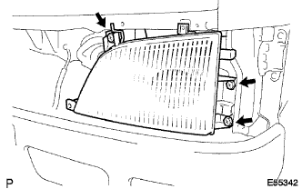
Remove the 3 screws.
-
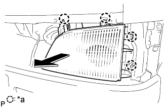
Text in Illustration *a Claw Release the 4 claws.
-
Disconnect connectors.
-
Pull out the headlight assembly LH forward and remove the headlight assembly LH.
-
Remove the socket cover.
-
Release the set spring, remove the headlight bulb No.1.
-
-
REMOVE HEADLAMP UNIT ASSEMBLY RH
-
REMOVE RADIATOR GRILLE BRACKET
-
Remove the bolt and radiator grille bracket.
-
-
SEPARATE CLUTCH MASTER CYLINDER TO FLEXIBLE HOSE TUBE
-
Using union nut wrench 10 mm, remove the clutch hose.
-
Remove the retainer.
-
-
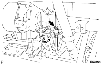
SEPARATE FRONT BRAKE TUBE NO.1
-
Using union nut wrench 10 mm, remove the brake tube.
-
Remove the retainer.
Note
Check the hose installation condition. (When installing a hose, never mistake the hose to be installed)
-
-
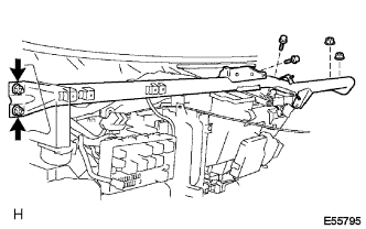
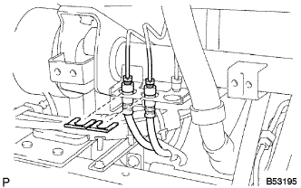
SEPARATE REAR BRAKE TUBE NO.1
-
Using union nut wrench 10 mm, remove the brake tube.
-
Remove the retainer.
-
-
SEPARATE ENGINE ROOM MAIN WIRE
-
CAB TILT UP
-
REMOVE TILT CAB SPRING SUPPORT ARM NO.1
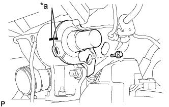
Text in Illustration *a Matchmarks
-
Place matchmarks tilt cab spring support arm No. 1.
-
Remove the bolt and tilt cab spring support arm No. 1.
-
-
CAB TILT DOWN
-
CAB HOLD
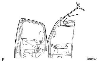
-
Put the wire on the roof panel of cab.
Note
Place the shop towel on the point contacting the cab in order not to avoid damage.
-
Tense the wire with the degree of force which does not pull the cab up.
Note
Do not pull cab up.
-
-
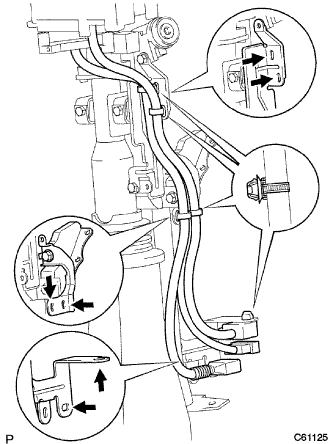
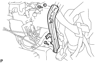
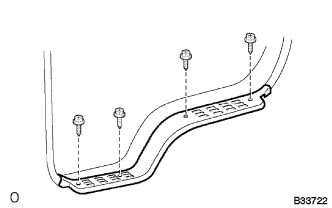
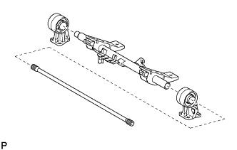
REMOVE TILT CAB TUBE SUB-ASSEMBLY NO.1
-
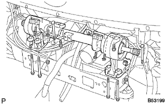
Remove the 12 bolts, 6 nuts and tilt cab tube sub-assembly No. 1.
-
Remove the front cab mounting LH and front cab mounting RH.
-