INSTRUMENT PANEL ASSEMBLY REMOVAL

-
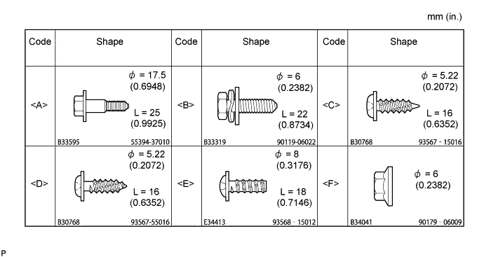
TABLE OF BOLT, SCREW AND NUT
Tech Tips
Indicate the bolts, screws and nuts, which are necessary for installation and removal of the instrument panel, in the illustration and the text with alphabets.
-
SEPARATE BATTERY NEGATIVE TERMINAL
-
INSPECT CENTER FRONT WHEEL
-
REMOVE HORN BUTTON ASSEMBLY (W/O SRS AIRBAG)
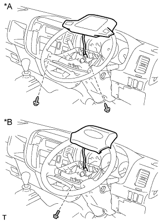
Text in Illustration *A Non-Tilt Column Assembly *B Tilt Column Assembly
-
Non-Tilt Column Assembly:
-
Remove the 2 screws and horn button assembly.
-
Disconnect the horn button connector.
-
-
Tilt Column Assembly:
-
Remove the screw and horn button assembly.
-
Disconnect the horn button connector.
-
-
-
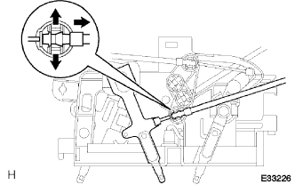
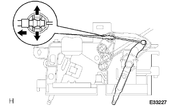
REMOVE HORN BUTTON ASSEMBLY (W/ SRS AIRBAG)
-
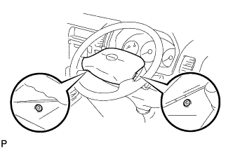
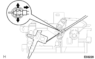
Place the front wheels facing straight ahead.
-
Using a torx socket wrench (T30), loosen the 2 torx screws until the groove along the screw circumference catches on the screw case.
-
Pull out the wheel pad from the horn button assembly.
-
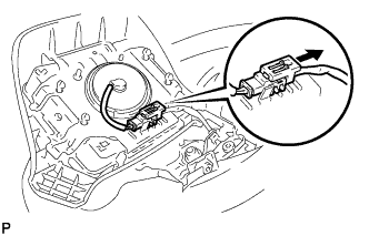
Disconnect the airbag connector and horn connector and remove the horn button assembly.
-
-
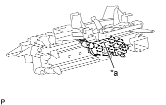
REMOVE STEERING WHEEL ASSEMBLY
-
Remove the steering wheel assembly set nut.
-
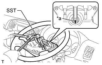
Text in Illustration *a Matchmark Place matchmarks on the steering wheel assembly and main shaft assembly.
-
Using SST, remove the steering wheel assembly.
- SST
- 09950-50013 ( 09951-05010, 09952-05010, 09953-05010, 09954-05021 )
-
-
REMOVE INSTRUMENT CLUSTER FINISH PANEL SUB-ASSEMBLY CENTER
-
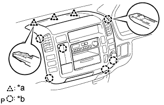
Text in Illustration *a 3 Clips *b 6 Claws Disengage the 3 clips and 6 claws.
-
Disconnect the connectors and remove the instrument cluster finish panel sub-assembly center.
-
-
REMOVE HEATER CONTROL LEVER KNOB (W/ HEATER)
-
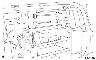
Remove the 4 heater control lever knobs.
-
-
REMOVE HEATER CONTROL NAME PLATE (W/ HEATER)
-
Text in Illustration *a 4 Claws Release the 4 claw fittings, remove the heater control name plate.
-
-
REMOVE HEATER OR BOOST VENTILATOR CONTROL ASSEMBLY (W/ HEATER)
-
Spread the clamp's claws of the defroster damper control cable and disconnect the inner cable.
-
Spread the clamp's claws of the air inlet damper control cable and disconnect the inner cable.
-
Text in Illustration *a Claw Release the claw fitting, remove the heater blower switch assembly and bulb.
-
Remove the 3 screws and heater or boost ventilator control assembly.
-
Spread the clamp's claws of the air mix damper control cable and disconnect the inner cable.
-
Disconnect the connector, remove the heater or boost ventilator control assembly.
-
-
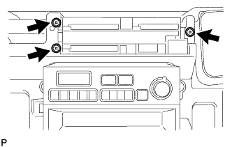
REMOVE RADIO BRACKET NO.1 & NO.2
-
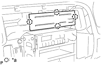
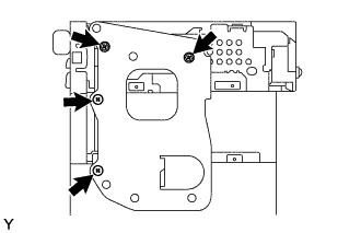
Remove the 4 screws and radio bracket No. 1.
-
-
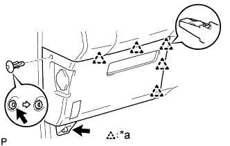
REMOVE GLOVE COMPARTMENT DOOR ASSEMBLY
-
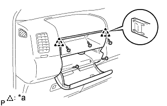
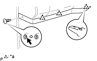
Text in Illustration *a 2 Claws Remove the 5 screws<D>.
-
Disengage the 2 claws and remove the glove compartment door assembly.
-
-
REMOVE INSTRUMENT COVER LWR (W/O HEATER)
-
Text in Illustration *a 3 Clips Disengage the 3 clips and remove the instrument cover LWR.
-
-
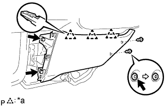
REMOVE INSTRUMENT COVER LWR (W/ HEATER)
-
Text in Illustration *a 5 Clips Remove the clip and bolt.
-
Disengage the 5 clips and remove the instrument cover LWR.
-
-
REMOVE INSTRUMENT COVER LOWER CENTER (W/HEATER)
-
Text in Illustration *a 3 Clips Remove the 2 clips and 2 bolts.
-
Disengage the 3 clips and remove the instrument cover lower center.
-
-
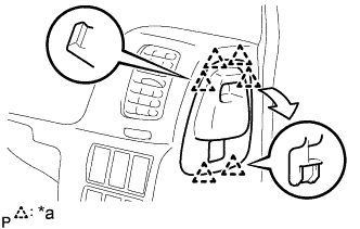
REMOVE INSTRUMENT CLUSTER FINISH PANEL
-
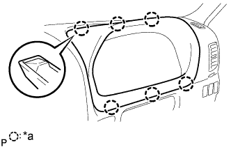
Text in Illustration *a 6 Claws Using a moulding remover, disengage the 6 claws and remove the instrument cluster finish panel.
-
-
REMOVE COMBINATION METER ASSEMBLY
-
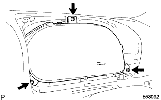
Remove the 3 screws.
-
Disconnect the connectors and remove the combination meter assembly.
-
-
REMOVE THROTTLE CONTROL CABLE KNOB (5L ENGINE TYPE)
-
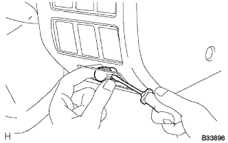
Using a screwdriver, put the claw for accel control w/ throttle cable assembly and remove the throttle control cable knob.
Tech Tips
Tape the screwdriver tip, before use.
-
-
REMOVE ACCEL CONTROL W/THROTTLE CABLE ASSEMBLY (5L ENGINE TYPE)
-
Remove the nut and accel control w/ throttle cable assembly.
-
-
REMOVE OIL RESERVOIR TANK COVER RH (RHD STEERING POSITION TYPE)
-
Text in Illustration *a 6 Claws Disengage the 6 claws and remove the oil reservoir tank cover RH.
-
-
REMOVE OIL RESERVOIR TANK COVER LH (LHD STEERING POSITION TYPE)
-
REMOVE INSTRUMENT PANEL SUB-ASSEMBLY
-
Remove the 2 clips.
-
Remove the 2 nuts<F> and 7 bolts<A><B>.
-
Disconnect the connectors and remove the instrument panel sub-assembly.
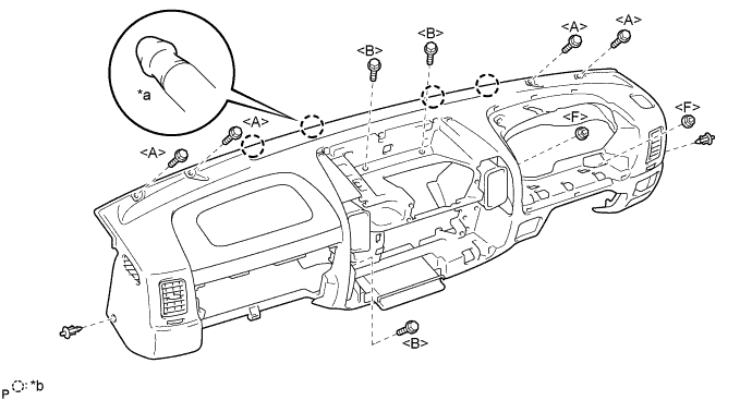
Text in Illustration *a Pin *b 4 Pins
-