POWER WINDOW CONTROL SYSTEM TERMINALS OF ECU
-
INSPECT POWER WINDOW REGULATOR MASTER SWITCH ASSEMBLY
-
Inspect the operation.
-
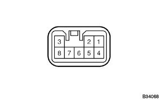
Check the voltage and continuity of each terminal in the driver's side connector, with the connector disconnected.
Tester connection Condition Specified condition 3 - Ground
(Input +B signal)
Ignition switch turned to ON from OFF 0 V → 10 - 14 V 5 - Ground Constant Continuity If the value is not as specified, the input side of the master switch may be defective.
-
-
Check the voltage of connector terminal with connector connected.
Tester connection Condition Specified condition 2 - Ground
(P/W, UP Output)
Ignition switch ON, Driver's side master switch OFF → UP (Manual operation) 0 V → 9 V or more ↑ Ignition switch ON, Driver's side door glass fully closed → Driver's side master switch UP (Automatic operation) → Door glass fully closed 0 V → 9 V or more → 0 V 1 - Ground
(P/W, DOWN Output)
Ignition switch ON, Driver's side master switch OFF → DOWN (Manual operation) 0 V → 9 V or more ↑ Ignition switch ON, Driver's side door glass fully closed → Driver's side master switch DOWN (Automatic operation) → Door glass fully opened 0 V → 9 V or more → 0 V 4 - Ground
(P/W, UP Output)
Ignition switch ON, Driver's side master switch OFF → UP (Manual operation) 0 V → 9 V or more 7 - Ground
(P/W, DOWN Output)
Ignition switch ON, Driver's side master switch OFF → DOWN (Manual operation) 0 V → 9 V or more 8 - Ground
(P/W, Lock Switch)
Ignition switch OFF, Window lock switch LOCK → UNLOCK Continuity
-