RADIO ANTENNA REMOVAL
-
REMOVE INSTRUMENT CLUSTER FINISH PANEL SUB-ASSEMBLY CENTER
-
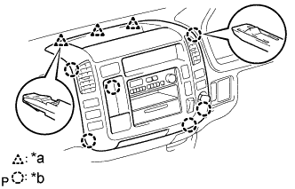
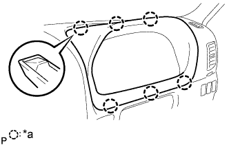
Text in Illustration *a 3 Clips *b 6 Claws Disengage the 3 clips and 6 claws.
-
Disconnect the connectors and remove the instrument cluster finish panel sub-assembly center.
-
-
REMOVE HEATER CONTROL LEVER KNOB (W/ HEATER)
-
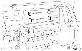
Remove the 4 heater control lever knobs.
-
-
REMOVE HEATER CONTROL NAME PLATE (W/ HEATER)
-
Text in Illustration *a 4 Claws Release the 4 claw fittings, remove the heater control name plate.
-
-
REMOVE HEATER OR BOOST VENTILATOR CONTROL ASSEMBLY (W/ HEATER)
-
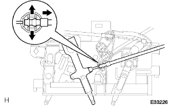
Spread the clamp's claws of the defroster damper control cable and disconnect the inner cable.
-
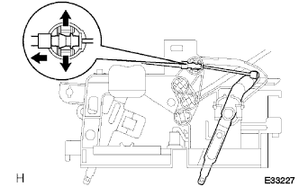
Spread the clamp's claws of the air inlet damper control cable and disconnect the inner cable.
-
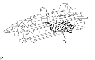
Text in Illustration *a Claw Release the claw fitting, remove the heater blower switch assembly and bulb.
-
Remove the 3 screws and heater or boost ventilator control assembly.
-
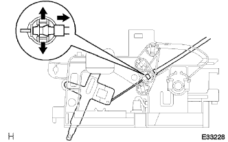
Spread the clamp's claws of the air mix damper control cable and disconnect the inner cable.
-
Disconnect the connector, remove the heater or boost ventilator control assembly.
-
-
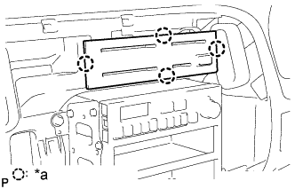
REMOVE RADIO RECEIVER ASSEMBLY

-
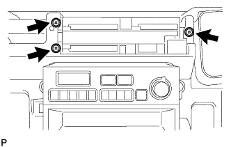
Remove the 4 bolts.
-
Disconnect the connector and remove the radio receiver assembly.
-
-
REMOVE INSTRUMENT CLUSTER FINISH PANEL
-
Text in Illustration *a 6 Claws Using a moulding remover, disengage the 6 claws and remove the instrument cluster finish panel.
-
-
REMOVE COMBINATION METER ASSEMBLY
-
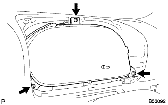
Remove the 3 screws.
-
Disconnect the connectors and remove the combination meter assembly.
-
-
REMOVE W/HOLDER ANTENNA ASSEMBLY
-
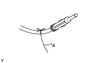
Text in Illustration *a String Tie the string at the tip of the cable of the w/holder antenna assembly.
-
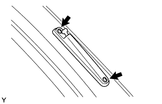
Remove the 2 screws.
-
Remove the w/holder antenna assembly.
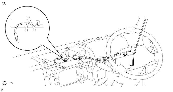
Text in Illustration *A RHD - - *a 4 Clamps - - 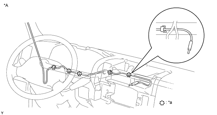
Text in Illustration *A LHD - - *a 5 Clamps - -
-