AUDIO AND VISUAL SYSTEM Sound Quality is Bad in All Modes
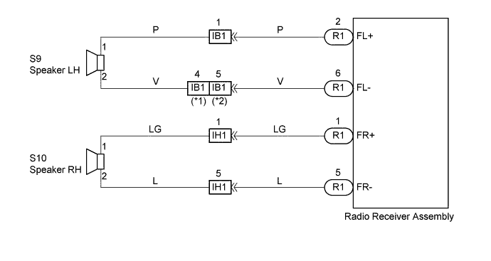
WIRING DIAGRAM
INSPECTION PROCEDURE
PROCEDURE
-
ADJUST SOUND QUALITY
-
Adjust the sound quality.
-
Operate the radio receiver assembly to adjust the sound quality.
Standard The operation returns to be normal.
-
OK 
BAD SOUND QUALITY
NG 
-
-
COMPARE IT WITH ANOTHER CAR OF SAME MODEL
-
Compare it with another vehicle of the same model.
-
Compare with the vehicle of the same type which does not have a trouble to see if there is any difference in the condition of trouble occurrence.
Standard No difference found.
-
OK
SETTING
NG
-
-
CHECK HARNESS AND CONNECTOR (RADIO RECEIVER ASSEMBLY - SPEAKER)
NG
REPAIR OR REPLACE HARNESS OR CONNECTOR
OK
-
INSPECT FRONT NO.1 SPEAKER ASSEMBLY
-
Preparation for Check
-
Disconnect the connector of the speaker.
-
-
Resistance Check
-
Check the resistance between the terminals of the speaker.
Standard value 2-9 Ω Note
The speaker should not be removed for checking.
-
NG
REPLACE FRONT NO.1 SPEAKER ASSEMBLY
OK
-
-
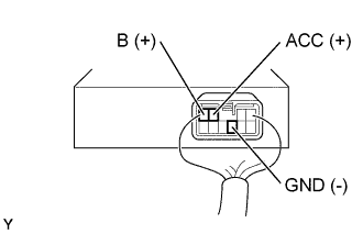
INSPECT RADIO RECEIVER ASSEMBLY (B, ACC, GND)
-
Remove radio receiver assembly with connectors still connected.
-
Check voltage.
-
Measure voltage between terminal B of radio receiver assembly and body ground.
Standard 10 - 14 V -
Measure voltage between terminal ACC of radio receiver assembly and body ground when ignition switch is turned to ACC.
Standard 10 - 14 V
-
-
Check continuity.
-
Check continuity exists between terminal GND of radio receiver assembly and body ground.
Standard Continuity exists
OK
CHECK AND REPLACE RADIO RECEIVER ASSEMBLY
NG 
REPAIR OR REPLACE HARNESS OR CONNECTOR
-