AUDIO AND VISUAL SYSTEM No Sound can be Heard from Speakers
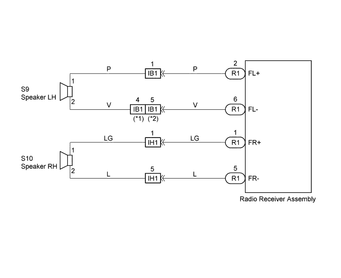
WIRING DIAGRAM
INSPECTION PROCEDURE
PROCEDURE
-
CHECK LCD (LIQUID CRYSTAL DISPLAY) FOR LIGHTING
-
LCD Illumination Check
-
Turn the ignition switch ACC.
-
Turn the radio receiver assembly ON.
Standard LCD illumination of the radio receiver assembly light.
-
NG 
INSPECT RADIO RECEIVER ASSEMBLY Click here
OK 
-
-
CONTROL FADER AND ADJUST SOUND BALANCE
-
Fader and Balance Adjustment
-
Operate the radio receiver assembly to adjust the fader and the balance to identify the speaker that does not sound.
(A) (B) A specific speaker does not sound. All speakers do not sound.
-
B
INSPECT RADIO RECEIVER ASSEMBLY Click here
A
-
-
INSPECT FRONT NO.1 SPEAKER ASSEMBLY
-
Preparation for Check
-
Disconnect the connector of the speaker.
-
-
Resistance Check
-
Check the resistance between the terminals of the speaker.
Note
The speaker should not be removed for checking.
Standard value 2-9 Ω
-
NG 
REPLACE FRONT NO.1 SPEAKER ASSEMBLY
OK
-
-
CHECK HARNESS AND CONNECTOR
NG
REPAIR OR REPLACE HARNESS OR CONNECTOR
OK 
CHECK AND REPLACE RADIO RECEIVER ASSEMBLY
-
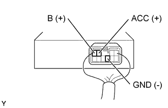
INSPECT RADIO RECEIVER ASSEMBLY
-
Remove radio receiver assembly with connectors still connected.
-
Check voltage.
-
Measure voltage between terminal B of radio receiver assembly and body ground.
Standard 10 - 14 V -
Measure voltage between terminal ACC of radio receiver assembly and body ground when ignition switch is turned to ACC.
Standard 10 - 14 V
-
-
Check continuity.
-
Check continuity exists between terminal GND of radio receiver assembly and body ground.
Standard Continuity exists
OK
CHECK AND REPLACE RADIO RECEIVER ASSEMBLY
NG
REPAIR OR REPLACE HARNESS OR CONNECTOR
-