AUDIO AND VISUAL SYSTEM Pressing Power Switch does not Turn on System
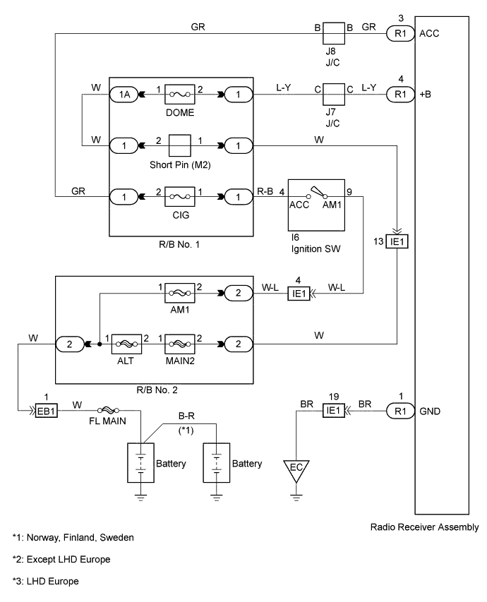
WIRING DIAGRAM
INSPECTION PROCEDURE
PROCEDURE
-
INSPECT RADIO RECEIVER ASSEMBLY (B, ACC, GND)
-
Remove the radio receiver assembly with connectors still connected.
-
Check voltage.
-
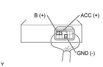
Measure voltage between terminal B of the radio receiver assembly and body ground.
Standard 10 - 14 V -
Measure voltage between terminal ACC of the radio receiver assembly and body ground when ignition switch is turned to ACC.
Standard 10 - 14 V
-
-
Check continuity.
-
Check that the continuity exists between terminal GND of radio receiver assembly and body ground.
Standard Continuity exists
-
NG 
REPAIR OR REPLACE HARNESS OR CONNECTOR
OK 
CHECK AND REPLACE RADIO RECEIVER ASSEMBLY
-