METER / GAUGE SYSTEM (for 1KD-FTV) Tachometer Malfunction
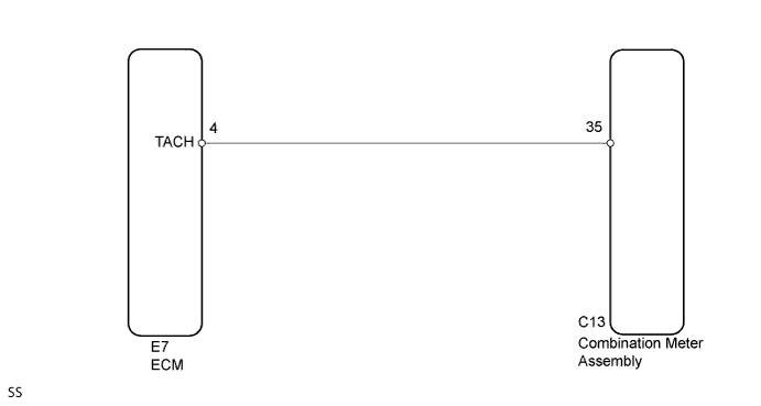
WIRING DIAGRAM
INSPECTION PROCEDURE
PROCEDURE
-
CHECK DTC (DTCS RELATED TO ECD SYSTEM)
-
Connect the intelligent tester to the DLC3.
-
Turn the ignition switch to ON.
-
Turn the intelligent tester on.
-
Enter the following menus: Powertrain / Engine and ECT / DTC /
-
Read the DTCs.
Result Result Proceed to No output A DTCs related to ECD system B
B 
GO TO DTC CHART (ECD SYSTEM)
A 
-
-
CHECK COMBINATION METER ASSEMBLY
-
Check the input signal waveform.
-
Remove the combination meter assembly with the connector still connected.
-
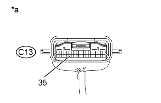
Connect the oscilloscope to Terminal C13-35 and the body ground.
-
Start the engine.
-
Text in Illustration *a Component with harness connected
(Combination Meter Assembly)
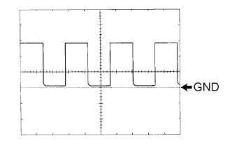
Check the signal waveform according to the condition(s) in the table below.
Item Condition Tool setting 5 V/DIV., 10 msec./DIV. Vehicle condition Engine idle speed OK The waveform is displayed as shown in the illustration
As the vehicle speed increases, the cycle of the signal waveform narrows.
-
NG 
CHECK HARNESS AND CONNECTOR (COMBINATION METER ASSEMBLY - ECM) Click here
OK 
REPLACE COMBINATION METER ASSEMBLY Click here
-
-
CHECK HARNESS AND CONNECTOR (COMBINATION METER ASSEMBLY - ECM)
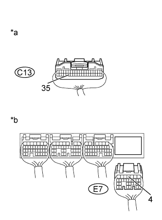
Text in Illustration *a Rear view of wire harness connector
(to Combination Meter Assembly)
*b Rear view of wire harness connector
(to ECM)
-
Disconnect Connector C13 of the combination meter assembly.
-
Disconnect Connector E7 of the ECM.
-
Measure the resistance according to the value(s) in the table below.
Standard resistance Tester Connection Switch Condition Specified Condition C13-35 - E7-4 (TACH) Always Below 1 Ω C13-35 or E7-4 (TACH) - Body ground Always 10 kΩ or higher -
Reconnect the connector of the combination meter assembly.
-
Reconnect the connector of the ECM.
NG
REPAIR OR REPLACE HARNESS OR CONNECTOR
OK
REPLACE ECM Click here
-