METER / GAUGE SYSTEM (for 1KD-FTV) Speedometer Malfunction
DESCRIPTION
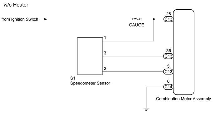
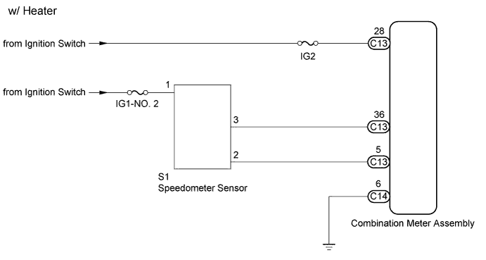
The combination meter assembly controls the speedometer in accordance with vehicle speed signals from the speedometer sensor.
WIRING DIAGRAM
INSPECTION PROCEDURE
Note
Inspect the fuses for circuits related to this system before performing the following inspection procedures.
PROCEDURE
-
INSPECT SPEEDOMETER SENSOR
-
Remove the speedometer sensor.
-
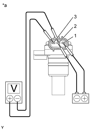
Text in Illustration *a Component without harness connected
(Speedometer Sensor)
Connect the positive (+) lead from the battery to terminal 1 and the negative (-) lead to terminal 2.
-
Connect the positive (+) lead from the tester to terminal 3 and the negative (-) lead to terminal 2.
-
Rotate the shaft.
-
Check that the voltage output varies between 0 V and 11 V between terminals 2 and 3.
Tech Tips
The voltage output oscillates more than 4 times every revolution of the speed sensor shaft. If the operation is not as specified, replace the sensor.
Result Result Proceed to NG A OK (w/o Heater) B OK (w/ Heater) C
B 
CHECK HARNESS AND CONNECTOR (SPEEDOMETER SENSOR - COMBINATION METER ASSEMBLY) Click here
C
CHECK HARNESS AND CONNECTOR (SPEEDOMETER SENSOR - COMBINATION METER ASSEMBLY) Click here
A 
REPLACE SPEEDOMETER SENSOR
-
-
CHECK HARNESS AND CONNECTOR (SPEEDOMETER SENSOR - COMBINATION METER ASSEMBLY)
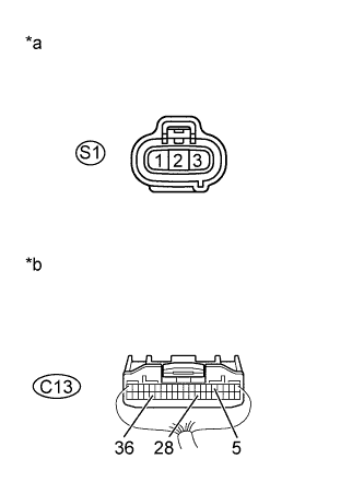
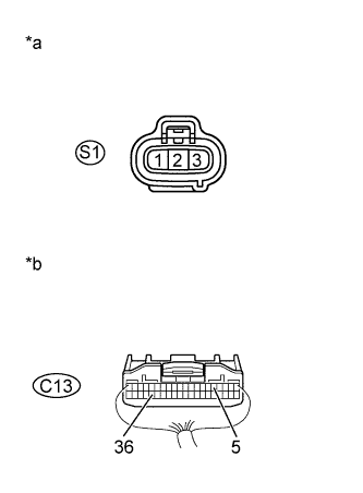
Text in Illustration *a Front view of wire harness connector
(to Speedometer Sensor)
*b Rear view of wire harness connector
(to Combination Meter Assembly)
-
Disconnect the C13 combination meter assembly connector.
-
Disconnect the S1 speedometer sensor connector.
-
Measure the resistance according to the value(s) in the table below.
Standard Resistance Tester Connection Condition Specified Condition C13-28 - S1-1 Always Below 1 Ω C13-36 - S1-3 Always Below 1 Ω C13-5 - S1-2 Always Below 1 Ω C13-36 - Body ground Always 10 kΩ or higher -
Measure the voltage according to the value(s) in the table below.
Standard Voltage Tester Connection Switch Condition Specified Condition S1-1 - Body ground Ignition switch off Below 1 V Ignition switch ON 11 to 14 V
NG 
REPAIR OR REPLACE HARNESS OR CONNECTOR
OK
REPLACE COMBINATION METER ASSEMBLY Click here
-
-
CHECK HARNESS AND CONNECTOR (SPEEDOMETER SENSOR - COMBINATION METER ASSEMBLY)
Text in Illustration *a Front view of wire harness connector
(to Speedometer Sensor)
*b Rear view of wire harness connector
(to Combination Meter Assembly)
-
Disconnect the C13 combination meter assembly connector.
-
Disconnect the S1 speedometer sensor connector.
-
Measure the resistance according to the value(s) in the table below.
Standard Resistance Tester Connection Condition Specified Condition C13-36 - S1-3 Always Below 1 Ω C13-5 - S1-2 Always Below 1 Ω C13-36 - Body ground Always 10 kΩ or higher -
Measure the voltage according to the value(s) in the table below.
Standard Voltage Tester Connection Switch Condition Specified Condition S1-1 - Body ground Ignition switch off Below 1 V Ignition switch ON 11 to 14 V
NG
REPAIR OR REPLACE HARNESS OR CONNECTOR
OK
REPLACE COMBINATION METER ASSEMBLY Click here
-