METER / GAUGE SYSTEM (for 1KD-FTV) Speedometer Malfunction
DESCRIPTION
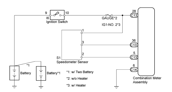
The combination meter assembly controls the speedometer in accordance with vehicle speed signals from the speedometer sensor.
WIRING DIAGRAM
INSPECTION PROCEDURE
Note
Inspect the fuses for circuits related to this system before performing the following inspection procedures.
PROCEDURE
-
INSPECT COMBINATION METER ASSEMBLY
-
Check the input signal waveform.
-
Remove the combination meter assembly with the connectors still connected.
-
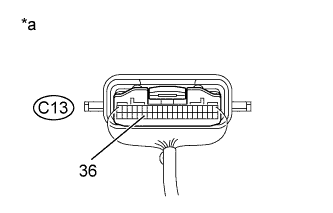
Connect the oscilloscope to Terminal C13-36 and body ground.
-
Start the engine.
-
Text in Illustration *a Component with harness connected
(Combination Meter Assembly)
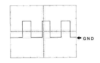
Check the signal waveform according to the condition (s) in the table below.
Item Condition Tool setting 5 V/DIV., 20 msec./DIV. Vehicle condition Driving at approximately 20 km/h (12 mph) OK The waveform is displayed as shown in the illustration
Tech Tips
As the vehicle speed increases, the cycle of the signal waveform narrows.
-
NG 
INSPECT COMBINATION METER ASSEMBLY Click here
OK 
REPLACE COMBINATION METER ASSEMBLY Click here
-
-
INSPECT COMBINATION METER ASSEMBLY
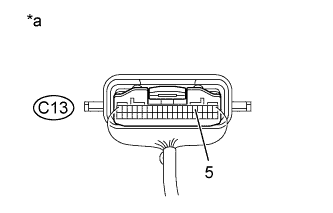
Text in Illustration *a Component with harness connected
(Combination Meter Assembly)
-
Measure the resistance according to the value(s) in the table below.
Standard resistance Tester Connection Condition Specified condition C13-5 - Body ground Always Below 1 Ω
NG 
REPLACE COMBINATION METER ASSEMBLY Click here
OK 
-
-
CHECK HARNESS AND CONNECTOR (SPEEDOMETER SENSOR - COMBINATION METER ASSEMBLY)
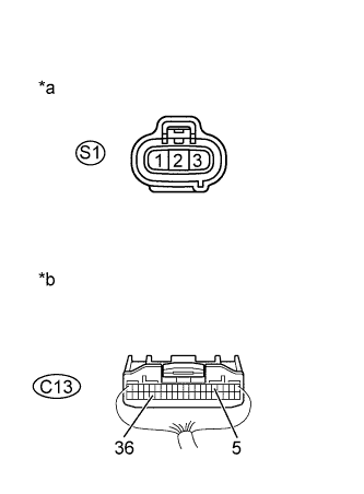
Text in Illustration *a Front view of wire harness connector
(to Speedometer Sensor)
*b Rear view of wire harness connector
(to Combination Meter Assembly)
-
Disconnect Connector C13 of the combination meter assembly.
-
Disconnect Connector S1 of the speedometer sensor.
-
Measure the resistance according to the value(s) in the table below.
Standard resistance Tester Connection Condition Specified Condition C13-28 - S1-1 Always Below 1 Ω C13-36 - S1-3 Always Below 1 Ω C13-5 - S1-2 Always Below 1 Ω C13-36 - Body ground Always 10 kΩ or higher -
Measure the voltage according to the value(s) in the table below.
Standard voltage Tester Connection Switch Condition Specified Condition S1-1 - Body ground Ignition switch off Below 1 V Ignition switch ON 11 to 14 V -
Reconnect the connector of the combination meter assembly.
-
Reconnect the connector of the speedometer sensor.
NG
REPAIR OR REPLACE HARNESS OR CONNECTOR
OK
REPLACE SPEEDOMETER SENSOR Click here
-