METER / GAUGE SYSTEM (for 1KD-FTV) Entire Combination Meter does not Operate
DESCRIPTION
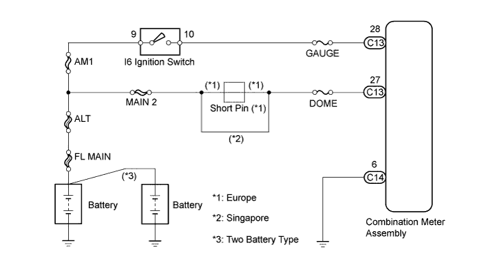
This circuit provides power to the combination meter assembly.
WIRING DIAGRAM
INSPECTION PROCEDURE
PROCEDURE
-
INSPECT FUSES (GAUGE, DOME)
-
Remove the GAUGE and DOME fuses from the R/B No. 1.
-
Measure the resistance.
Standard resistance Below 1 Ω -
Reinstall the GAUGE and DOME fuses.
NG 
REPLACE FUSE
OK 
-
-
CHECK HARNESS AND CONNECTOR (COMBINATION METER - BATTERY, BODY GROUND)
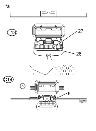
Text in Illustration *a Rear view of wire harness connector
(to Combination Meter Assembly)
-
Disconnect the C13 and C14 connectors from the combination meter assembly.
-
Measure the resistance.
Standard resistance Tester Connection Specified condition C14-6 - Body ground Below 1 Ω -
Measure the voltage.
Standard voltage Tester Connection Condition Specified Condition C13-28 - Body ground Ignition switch ON 11 to 14 V C13-27 - Body ground Always 11 to 14 V -
Reconnect the connectors.
NG
REPAIR OR REPLACE HARNESS OR CONNECTOR
OK 
REPLACE COMBINATION METER ASSEMBLY
-