METER / GAUGE SYSTEM (for 1KD-FTV) ON-VEHICLE INSPECTION

-
INSPECT SPEEDOMETER
-
Check the operation.
-
Using a speedometer tester, inspect the speedometer and confirm that the speedometer readings are within the acceptable range. Also check the odometer operation.
Reference km/h (Singapore) Standard Indication Acceptable Range 20 km/h 18 to 22 km/h 40 km/h 36 to 44 km/h 60 km/h 54 to 66 km/h 80 km/h 72 to 88 km/h 100 km/h 90 to 110 km/h 120 km/h 108 to 132 km/h 140 km/h 126 to 154 km/h km/h (Europe) Standard Indication Acceptable Range 20 km/h 20 to 26 km/h 40 km/h 40 to 48 km/h 60 km/h 60 to 70 km/h 80 km/h 80 to 92 km/h 100 km/h 100 to 114 km/h 120 km/h 120 to 136 km/h 140 km/h 140 to 158 km/h mph (Europe) Standard Indication Acceptable Range 20 mph 20.0 to 24.4 mph 40 mph 40.0 to 46.4 mph 60 mph 60.0 to 68.4 mph 80 mph 80.0 to 90.4 mph Note
Tire wear and excessively high or low tire pressure affect speedometer indications.
-
Check the deflection of the speedometer indicator.
Reference Below 0.5 km/h (0.3 mph)
-
-
-
INSPECT SPEEDOMETER SENSOR
-
Remove the combination meter assembly with the connectors still connected.
-
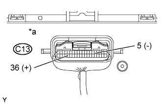
Connect the oscilloscope to the terminals C13-36 and C13-5.
-
Start the engine.
-
Text in Illustration *a Component with harness connected
(Combination Meter Assembly)
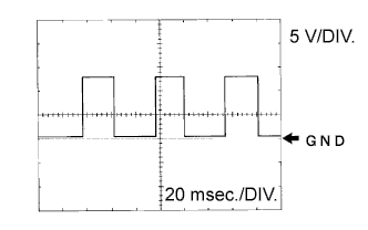
Check for standard signal waveform.
Item Condition Tool setting 5 V/DIV, 20 ms/DIV Vehicle condition Driving at approximately. 20 km/h (12 mph) OK AS shown in the illustration Tech Tips
As the vehicle speed increases, the cycle of the signal waveform narrows.
-
-
INSPECT TACHOMETER (w/ Tachometer)
-
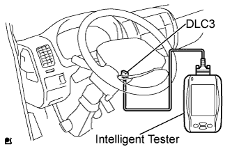
Connect the intelligent tester to the DLC3.
-
Turn the ignition switch ON.
-
Turn the intelligent tester ON.
-
Select the following menu items: Powertrain / Engine and ECT / Data List.
-
Read the Data List.
ECM Item Measurement Item/ Range(Display) Normal Condition Diagnostic Note Engine speed Engine speed / Min.: 0 rpm, Max.: 12,750 rpm Approximately same as actual engine speed (When engine is running) - -
Compare the engine speed displayed on the tester with the tachometer reading.
Reference Standard Indication Acceptable Range
[Data in ( ) are for reference]
700 r/min 630 to 770 r/min 1,000 r/min (900 to 1,100 r/min) 2,000 r/min (1,850 to 2,150 r/min) 3,000 r/min 2,800 to 3,200 r/min 4,000 r/min (3,800 to 4,200 r/min) 5,000 r/min 4,800 to 5,200 r/min
-
-
INSPECT FUEL RECEIVER GAUGE
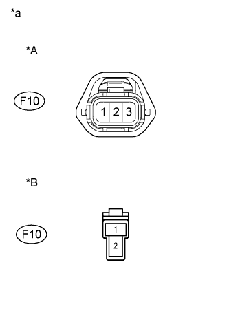
Text in Illustration *A for Europe *B for Singapore *a Front view of wire harness connector
(to Fuel Sender Gauge Assembly)
-
Europe:
-
Disconnect the F10 fuel sender gauge connector.
-
Turn the ignition switch ON, then check the position of the receiver gauge needle.
Needle position EMPTY -
Connect terminals 2 and 3 on the wire harness side connector of the fuel sender gauge.
Needle position FULL -
Reconnect the fuel sender gauge connector.
-
-
Singapore:
-
Disconnect the F10 fuel sender gauge connector.
-
Turn the ignition switch ON, then check the position of the receiver gauge needle.
Needle position EMPTY -
Connect terminals 1 and 2 on the wire harness side connector of the fuel sender gauge.
Needle position FULL -
Reconnect the fuel sender gauge connector.
-
-
-
INSPECT FUEL LEVEL WARNING LIGHT (w/ Fuel Level Warning Light)
-
Disconnect the F10 fuel sender gauge connector.
-
Turn the ignition switch ON, and check the fuel level warning light.
OK Fuel level warning light illuminates. -
Reconnect the fuel sender gauge connector.
-
-
INSPECT ENGINE OIL PRESSURE WARNING LIGHT
-
Disconnect the O1 engine oil pressure switch connector.
-
Turn the ignition switch ON.
-
Ground the terminal of the wire harness side connector, then check the engine oil pressure warning light.
OK Engine oil pressure warning light illuminates. -
Reconnect the engine oil pressure switch connector.
-
-
INSPECT BRAKE WARNING LIGHT
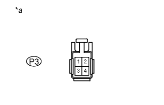
Text in Illustration *a Front view of wire harness connector
(to Parking Brake Switch Assembly)
-
Inspect the parking brake warning light.
-
Disconnect the P3 parking brake switch connector.
-
Turn the ignition switch ON.
-
Ground the terminal 2 of the wire harness side connector, then check the parking brake warning light.
OK Brake warning light illuminates. -
Reconnect the parking brake switch connector.
-
-
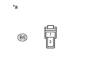
Text in Illustration *a Front view of wire harness connector
(to Brake Fluid Level Warning Switch Assembly)
Inspect the brake fluid level warning light.
-
Disconnect the B5 brake fluid level warning switch connector.
-
Turn the ignition switch ON.
-
Connect a terminal to the other terminal of the wire harness side connector, then check the brake fluid level warning light.
OK Brake warning light illuminates. -
Reconnect the brake fluid level warning switch connector.
-
-
Inspect the brake vacuum warning light.
-
Disconnect the B2 brake vacuum warning switch connector.
-
Turn the ignition switch ON.
-
Ground the terminal of the wire harness side connector, then check the brake vacuum warning light.
OK Brake warning light illuminates. -
Reconnect the brake vacuum warning switch connector.
-
-
-
INSPECT BRAKE FLUID LEVEL WARNING SWITCH
-
Remove the reservoir tank cap and strainer.
-
Disconnect the brake fluid level warning switch connector.
-
Measure the resistance between the terminals.
Standard resistance Float inside reservoir tank is in high position (switch OFF) 10 kΩ or higher -
Use a syphon or a similar tool to drain fluid out of the reservoir tank.
-
Measure the resistance between the terminals.
Standard resistance Float inside reservoir tank is in low position (switch ON) Below 1 Ω -
Pour the fluid back into the reservoir tank.
-
Reconnect the brake fluid level warning switch connector.
-
Reinstall the reservoir tank cap and strainer.
-
-
INSPECT T-BELT WARNING
-
T-BELT mode display
-
Turn the ODO/TRIP display screen to ODO, and turn the ignition switch OFF.
-
While pressing the trip switch, turn the ignition switch ON and hold it for 5 seconds.
-
Release the trip switch, then press the trip switch again within 5 seconds.
-
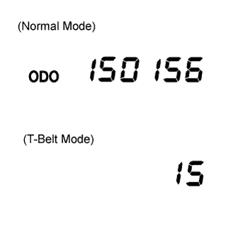
Transfer to T-BELT mode, and the following initial setting value is displayed.
km: 15 (0,000 km)
mile: 9 (0,000 mile)
Tech Tips
If the meter has been replaced before, the displayed value might not be the initial setting value.
-
-
Rewriting replacement setting value.
Press the trip switch and rewrite the replacement setting value.
Conditions Setting value When a belt is replaced km: 15 (0,000 km)
mile: 9 (0,000 mile)
When a meter is replaced km: (15 (0,000 km)) - (km when the meter is replaced))
mile: (9 (0,000 mile)) - (mileage when the meter is replaced))
Tech Tips
When pressing the trip switch, the displayed value is changed to 1 (0,000 km) / 1 (0,000 mile) for the first time and after this, increases in increments of 1 (0,000 km) / 1 (0,000 mile) up to 20 (0,000 km) / 20 (0,000 mile). If switch operation is not performed for more than 30 seconds, the setting value will not be changed, the display screen turns to "ODO", and the mode returns to the normal mode.
-
T-BELT mode completion
Note
If T-BELT mode is completed, even though belt replacement or meter replacement has not been performed, the T-BELT warning is reset.
-
After setting the replacement setting value, hold the trip switch ON for more than 5 seconds, then release the trip switch.
-
Check that the display has changed to "ODO" and warning light has gone OFF.
-
-
-
INSPECT OIL MAINTENANCE INDICATOR RESETTING PROCEDURE (w/ Oil Maintenance Indicator)
Note
After an engine oil and filter change, even though the system has been reset, the warning light does not go out, or comes on again soon.
-
Resetting the system
-
Turn the ignition switch ON.
-
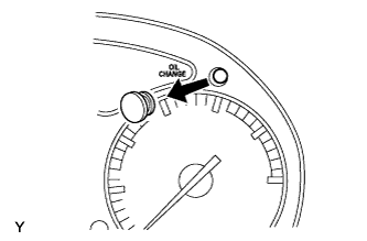
Remove the reset switch cover from the combination meter.
-
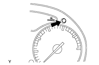
Push the reset switch for at least one second with a thin object such as a pen tip.
-
The engine oil change reminder light will go out.
Note
Reset the system only after an engine oil and filter change. If you reset the system at any other time, it cannot inform you of the correct time to change oil and oil filter.
Tech Tips
-
The system must also be reset if an engine oil and filter change is performed before the light comes on. In this case, when you push the reset switch, the light will come on. When you stop pressing, the light will go out.
-
If you push the switch for too short a time, the engine oil change reminder light may not go out. If this happens, reset the above procedure.
-
-
-