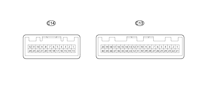
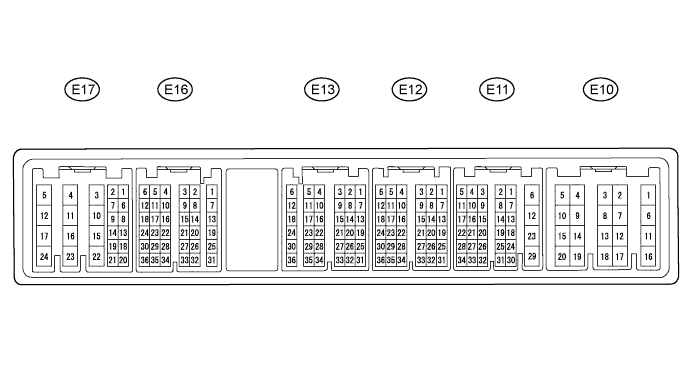
METER / GAUGE SYSTEM (for 1KD-FTV) TERMINALS OF ECU

-
CHECK COMBINATION METER ASSEMBLY
-
Measure the resistance, voltage and check for pulse according to the value(s) in the table below.
Terminal No. (Symbol) Wiring Color Terminal Description Condition Specified Condition C13-2 - Body ground R-G - Body ground Hi beam signal Hi beam indicator light
OFF → ON
Below 1 V → 11 to 14 V C13-3 - Body ground Y-R - Body ground Glow signal Glow indicator
ON → OFF
Below 1 V → 5 to 7 V C13-5 - Body ground BR - Body ground Ground (Vehicle speed sensor) Always Below 1 V C13-12 - Body ground*1 L-W - Body ground Oil condition signal Ignition switch ON Pulse generation C13-14 - Body ground P-L - Body ground Oil pressure signal Oil pressure warning light
ON → OFF
Below 1 V → 10 to 14 V C13-16 - Body ground B-Y - Body ground Brake warning light signal Brake warning light
OFF → ON
10 to 14 V → Below 1 V C13-17 - Body ground G-Y - Body ground Right turn signal Right turn indicator light
OFF → ON
Below 1 V → 11 to 14 V C13-18 - Body ground W - Body ground Engine coolant temperature signal from ECM Ignition switch ON Pulse generation C13-24 - Body ground G-B - Body ground Left turn signal Left turn indicator light
OFF → ON
Below 1 V → 11 to 14 V C13-25 - Body ground W-B - Body ground Ground Always Below 1 V C13-26 - Body ground Y - Body ground Fuel sender signal Ignition switch ON 10 to 14 V C13-27 - Body ground L-Y - Body ground Battery Always 11 to 14 V C13-28 - Body ground R - Body ground Ignition switch signal Ignition switch
OFF → ON
Below 1 V → 11 to 14 V C13-29 - Body ground G - Body ground Illumination signal Headlight dimmer switch
OFF → ON
Below 1 V → 11 to 14 V C13-30 - Body ground W-B - Body ground Ground Always Below 1 V C13-31 - Body ground BR - Body ground Ground Always Below 1 V C13-32 - Body ground R-W - Body ground Front door LH courtesy light switch signal Front door LH open Below 1 V Front door LH closed Pulse generation C13-35 - Body ground B - Body ground Engine speed signal from ECM Engine idling Pulse generation
(See waveform 1)
C13-36 - Body ground V-Y - Body ground Vehicle speed sensor signal Driving at approximately 20 km/h (12 mph) Pulse generation
(See waveform 2)
C13-37 - Body ground V-W - Body ground Vehicle speed signal output to ECM Driving at approximately 20 km/h (12 mph) Pulse generation
(See waveform 2)
C13-39 - Body ground B-R - Body ground Engine oil level warning switch signal Oil level warning light
OFF → ON
Below 1 V → 11 to 14 V C13-40 - Body ground*3 R-Y - Body ground ABS warning light signal ABS warning light
OFF → ON
7 to 11 V → Below 1 V C13-40 - Body ground*4 R-Y - Body ground Ground Always Below 1 V C14-3 - Body ground*2 V-R - Body ground Fuel sedimenter switch signal Fuel filter warning light
OFF → Blinking
11 to 14 V → Below 1 V C14-6 - Body ground BR - Body ground Ground Always Below 1 V C14-7 - Body ground Y - Body ground Charge signal Ignition switch ON (engine stopped)
→
Engine idling
Below 1 V → 11 to 14 V C14-8 - Body ground R - Body ground Ignition switch signal Ignition switch
OFF → ON
Below 1 V → 11 to 14 V C14-10 - Body ground*6 V - Body ground DPF warning light signal DPF warning light
OFF → ON
11 to 14 V → Below 1 V C14-12 - Body ground W - Body ground Fuel filter warning switch signal Fuel filter warning light
OFF → ON
11 to 14 V → Below 1 V C14-19 - Body ground*5 B-Y - Body ground SRS warning switch signal SRS warning light
OFF → ON
11 to 14 V → 3 to 6 V C14-23 - Body ground W-L - Body ground MIL signal MIL
OFF → ON
10 to 14 V → Below 1 V
-
*1: w/ Heater
-
*2: w/o Heater
-
*3: w/ ABS
-
*4: w/o ABS
-
*5: w/ Airbag System
-
*6: w/ DPF
-
-
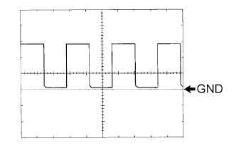
Waveform 1: Using an oscilloscope, check the signal waveform.
Item Condition Terminal No. C13-35 - Body ground Tool setting 5 V/DIV., 10 msec./DIV. Vehicle condition Engine idling Tech Tips
As the vehicle speed increases, the cycle of the signal waveform narrows.
-
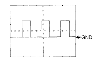
Waveform 2: Using an oscilloscope, check the signal waveform.
Item Condition Terminal No. C13-36 - Body ground Tool setting 5 V/DIV., 20 msec./DIV. Vehicle condition Driving at approximately 20 km/h (12 mph)
-
-
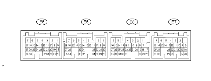
CHECK ECM (w/o EGR Cooler Bypass Valve)
-
Measure the resistance, voltage and check for pulse according to the value(s) in the table below.
Terminal No. (Symbol) Wiring Color Terminal Description Condition Specified Condition E6-19 (THW) - E6-28 (E2) B-Y - BR Engine coolant temperature signal Ignition switch ON Pulse generation E7-2 (THWO) - E6-7 (E01) R-L - BR Engine coolant temperature signal Ignition switch ON Pulse generation E7-4 (TACH) -E6-7 (E01) B - BR Engine speed signal Engine idling Pulse generation (See waveform 3) E7-14 (GIND) - Body ground Y-R - Body ground Glow signal Glow indicator ON→ OFF Below 1 V → 11 to 14 V -
Waveform 3: Using an oscilloscope, check the signal waveform.
Item Condition Terminal No. E7-4 (TACH) - E6-7 (E01) Tool setting 5 V/DIV., 10 msec./DIV. Vehicle condition Engine idling Tech Tips
As the vehicle speed increases, the cycle of the signal waveform narrows.
-
-
CHECK ECM (w/ DPF)
-
Measure the resistance, voltage and check for pulse according to the value(s) in the table below.
Terminal No. (Symbol) Wiring Color Terminal Description Condition Specified Condition E13-5 (THW) - E13-11 (ETHW) B-Y - BR Engine coolant temperature signal Idling, engine coolant temperature at 80°C (176°F) 0.2 to 1.0 V E17-18 (TACH) - E10-1 (E1) B - BR Engine speed signal Engine idling Pulse generation (See waveform 4) E16-19 (GIND) - Body ground G-W - Body ground Glow signal Glow indicator ON → OFF Below 1 V → 11 to 14 V E16-34 (OPID) - E10-12 (E01) P-L - BR DPF warning light signal DPF warning light ON → OFF Below 1 V → 11 to 14 V -
Waveform 4: Using an oscilloscope, check the signal waveform.
Item Condition Terminal No. E17-18 (TACH) - E10-12(E01) Tool setting 5 V/DIV., 10 msec./DIV. Vehicle condition Engine idling Tech Tips
As the vehicle speed increases, the cycle of the signal waveform narrows.
-
-
CHECK COMBINATION METER INNER CIRCUIT
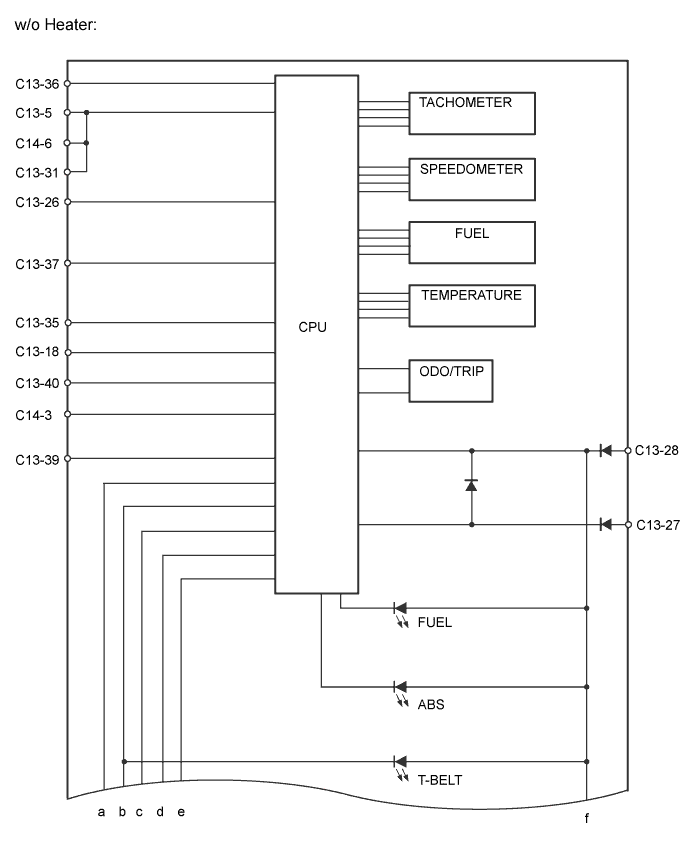
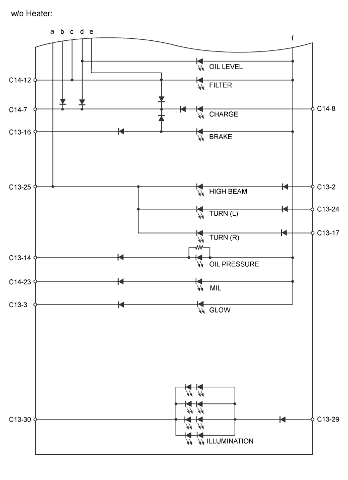
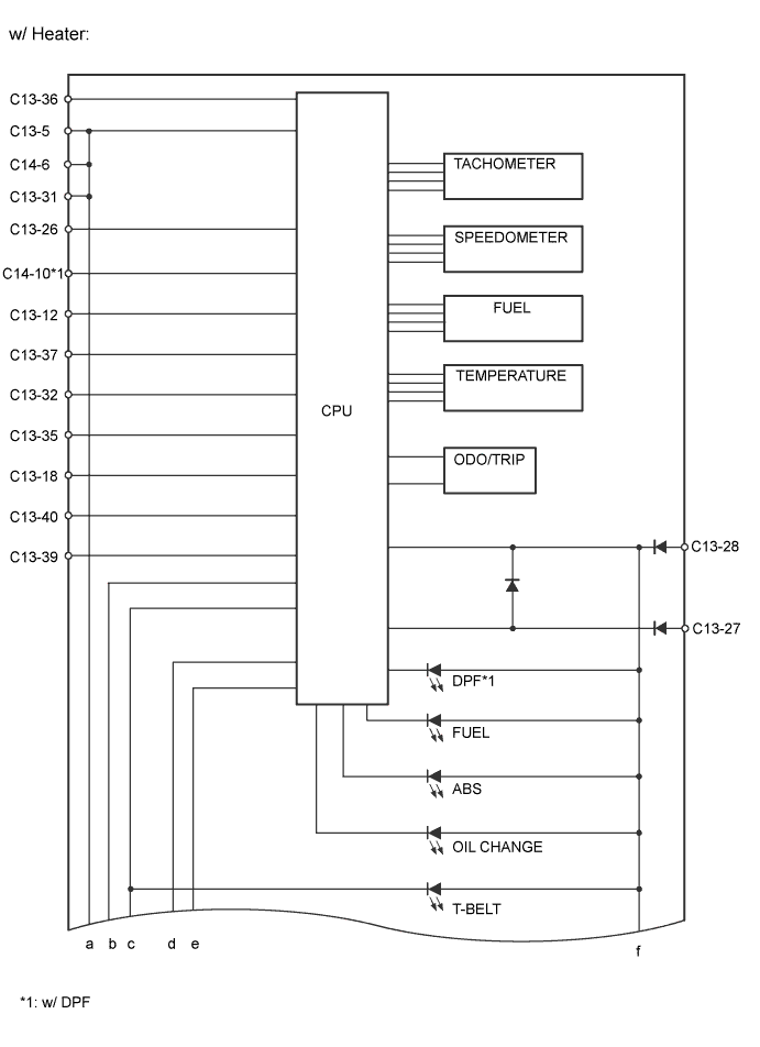
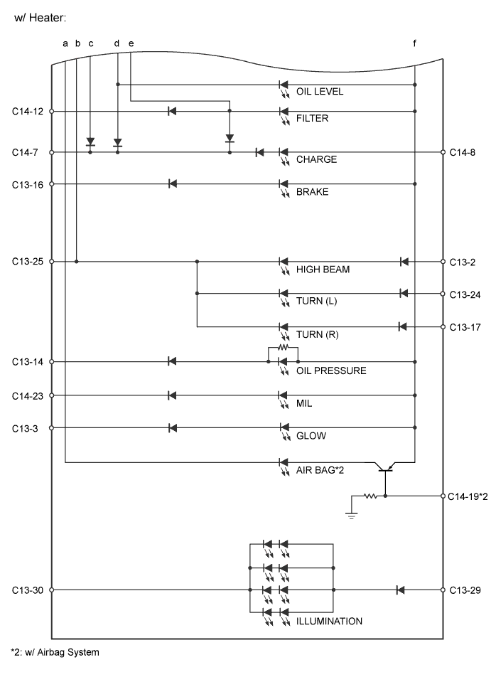
Table of terminal connection Terminal No. (Symbol) Wire Harness Side C13 2 H-LP Fuse (HI RH)*6
Headlight (HI LH and RH)*7
3 ECM 5 Speedometer Sensor 12 ECM*1 14 Engine Oil Pressure Switch Assembly 16 Parking Brake Switch Assembly, Vacuum Warning Switch Assembly and Brake Master Cylinder Reservoir Sub-Assembly (Brake Fluid Level Warning Switch) 17 Combination Switch 18 ECM 24 Combination Switch 25 Ground 26 Fuel Sender Gauge Assembly 27 DOME Fuse 28 IG1 NO. 2 Fuse*1
GAUGE Fuse*2
29 TAIL Relay 30 Ground 31 Ground 31 Front Door Courtesy Light Switch Assembly 35 ECM 36 Speedometer Sensor 37 ECM 39 Engine Oil Level Sensor (Engine Oil Level Warning Switch) 40 Skid Control ECU Assembly (ABS ECU)*3
Ground*4
C14 3*2 Level Warning Switch (Fuel Sedimenter Switch) 6 Ground 7 Generator Assembly (Alternator) 8 IG1 NO. 2 Fuse*1
GAUGE Fuse*2
10 ECM 12 Fuel Filter Warning Switch 19*5 Airbag ECU Assembly 23 ECM *1: w/ Heater
*2: w/o Heater
*3: w/ ABS
*4: w/o ABS
*5: w/ Airbag System
*6: w/ Daytime Running Light Control
*7: w/o Daytime Running Light System