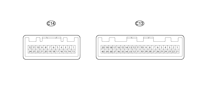
METER / GAUGE SYSTEM (for 1KD-FTV) TERMINALS OF ECU

-
CHECK COMBINATION METER ASSEMBLY
-
Measure the resistance and voltage according to the value(s) in the table below.
Standard Terminal No. (Symbol) Terminal Description Condition Specified Condition C13-2 - Body ground Hi beam signal Hi beam indicator light
off → on
Below 1 V → 11 to 14 V C13-3 - Body ground Glow signal Glow indicator
on → off
Below 1 V → 11 to 14 V C13-5 - Body ground Ground (Vehicle speed sensor) Always Below 1 V C13-11 - Body ground*1 Oil change light reset switch signal Oil change light reset switch
off → on
1 MΩ or higher → Below 1 Ω C13-12 - Body ground*1 Oil change light signal Oil change light
off → on
11 to 14 V → Below 1 V C13-14 - Body ground Oil pressure signal Oil pressure warning light
on → off
Below 1 V → 11 to 14 V C13-16 - Body ground Brake warning light signal Brake warning light
off → on
11 to 14 V → Below 1 V C13-17 - Body ground Right turn signal Right turn indicator light
off → on
Below 1 V → 11 to 14 V C13-18 - Body ground Engine coolant temperature signal from ECM Ignition switch ON Pulse generation C13-24 - Body ground Left turn signal Left turn indicator light
off → on
Below 1 V → 11 to 14 V C13-25 - Body ground Ground Always Below 1 V C13-26 - Body ground Fuel sender signal Ignition switch ON 11 to 14 V C13-27 - Body ground Battery Always 11 to 14 V C13-28 - Body ground Ignition switch signal Ignition switch
off → ON
Below 1 V → 11 to 14 V C13-29 - Body ground Illumination signal Headlight dimmer switch
off → on
Below 1 V → 11 to 14 V C13-30 - Body ground Ground Always Below 1 V C13-31 - Body ground Ground Always Below 1 V C13-35 - Body ground Engine speed signal from ECM Engine running Pulse generation
(See waveform 1)
C13-36 - Body ground Vehicle speed sensor signal Ignition switch ON and drive wheel turned slowly Pulse generation
(See waveform 2)
C13-37 - Body ground Vehicle speed signal output to ECM Ignition switch ON and drive wheel turned slowly Pulse generation
(See waveform 2)
C13-38 - Body ground*1 Vehicle speed signal output to Oil Monitor System Ignition switch ON and drive wheel turned slowly Pulse generation
(See waveform 2)
C13-39 - Body ground Engine oil level warning switch signal Oil level warning light
off → on
Below 1 V → 11 to 14 V C13-40 - Body ground*3 ABS warning light signal ABS warning light
off → on
11 to 14 V → Below 1 V C13-40 - Body ground*4 Ground Always Below 1 V C14-3 - Body ground*2 Fuel sedimenter switch signal Fuel filter warning light
off → Blinking
11 to 14 V → Below 1 V C14-6 - Body ground Ground Always Below 1 V C14-7 - Body ground Charge signal Ignition switch ON (engine stopped)
→
Engine idling
Below 1 V → 11 to 14 V C14-8 - Body ground Ignition switch signal Ignition switch
off → ON
Below 1 V → 11 to 14 V C14-12 - Body ground Fuel filter warning switch signal Fuel filter warning light
off → on
11 to 14 V → Below 1 V C14-19 - Body ground*5 SRS warning switch signal SRS warning light
off → on
11 to 14 V → Below 1 V C14-23 - Body ground MIL signal MIL
off → on
11 to 14 V → Below 1 V *1: w/ Heater
*2: w/o Heater
*3: w/ ABS
*4: w/o ABS
*5: w/ Airbag system
-
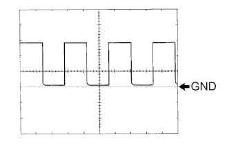
Waveform 1: Using an oscilloscope, check the signal waveform.
Item Content Terminal No. C13-35 - Body ground Tool setting 5 V/DIV., 10 msec./DIV. Vehicle condition Engine idling Tech Tips
As the vehicle speed increases, the cycle of the signal waveform narrows.
-
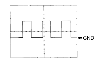
Waveform 2: Using an oscilloscope, check the signal waveform.
Item Condition Terminal No. C13-36 - Body ground Tool setting 5 V/DIV., 20 msec./DIV. Vehicle condition Driving at approximately 20 km/h (12 mph)
-
-
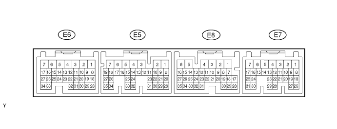
CHECK ECM
-
Measure the resistance and voltage according to the value(s) in the table below.
Standard Terminal No. (Symbol) Terminal Description Condition Specified Condition E6-19 (THW) - E6-28 (E2) Engine coolant temperature signal Ignition switch ON Pulse generation E7-2 (THWO) - E6-7 (E01) Engine coolant temperature signal Ignition switch ON Pulse generation E7-4 (TACH) -E6-7 (E01) Engine speed signal Engine running Pulse generation (See waveform 1) E7-14 (GIND) - Body ground Glow signal Glow indicator on→ off Below 1 V → 11 to 14 V *1: w/ Heater
*2: w/o Heater
-
Waveform 3: Using an oscilloscope, check the signal waveform.
Item Content Terminal No. E7-4 (TACH) -E6-7 (E01) Tool setting 5 V/DIV., 10 msec./DIV. Vehicle condition Engine idling Tech Tips
As the vehicle speed increases, the cycle of the signal waveform narrows.
-
-
CHECK COMBINATION METER INNER CIRCUIT
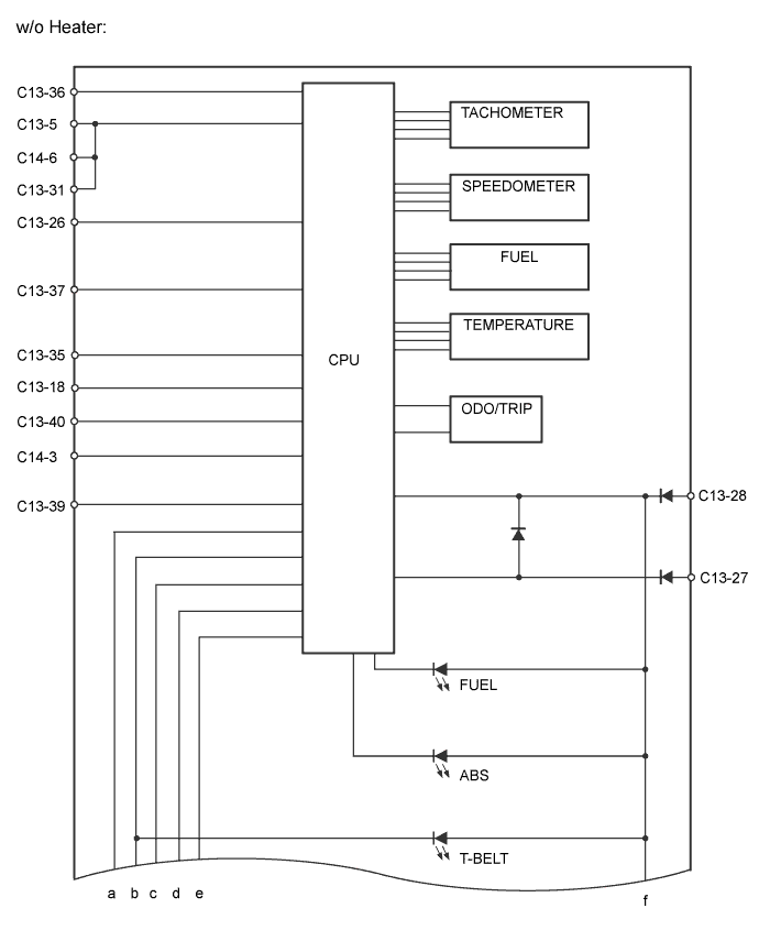
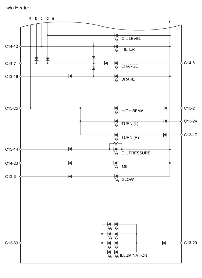
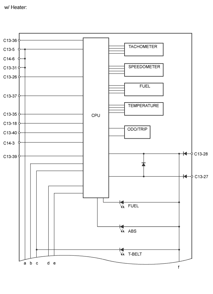
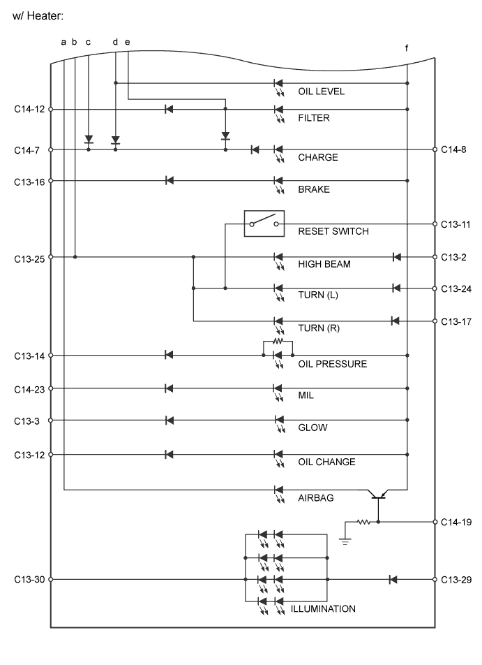
Table of terminal connection Terminal No. (Symbol) Wire Harness Side C13 2 H-LP Fuse (HI RH)*6
Headlight (HI LH and RH)*7
3 ECM 5 Speedometer Sensor 11 Condition Indicator ECU Assembly (Oil Monitor ECU)*1 12 Condition Indicator ECU Assembly (Oil Monitor ECU)*1 14 Engine Oil Pressure Switch Assembly 16 Parking Brake Switch Assembly, Vacuum Warning Switch Assembly and Brake Master Cylinder Reservoir Sub-Assembly (Brake Fluid Level Warning Switch) 17 Combination Switch 18 ECM 24 Combination Switch 25 Ground 26 Fuel Sender Gauge Assembly 27 DOME Fuse 28 IG1 NO. 2 Fuse*1
GAUGE Fuse*2
29 TAIL Relay 30 Ground 31 Ground 35 ECM 36 Speedometer Sensor 37 ECM 38 Condition Indicator ECU Assembly (Oil Monitor ECU)*1 39 Engine Oil Level Sensor (Engine Oil Level Warning Switch) 40 Skid Control ECU Assembly (ABS ECU)*3
Ground*4
C14 3*2 Level Warning Switch (Fuel Sedimenter Switch) 6 Ground 7 Generator Assembly (Alternator) 8 IG1 NO. 2 Fuse*1
GAUGE Fuse*2
12 Fuel Filter Warning Switch 19*5 Airbag ECU Assembly 23 ECM *1: w/ Heater
*2: w/o Heater
*3: w/ ABS
*4: w/o ABS
*5: w/ Airbag system
*6: w/ Daytime running light Control
*7: w/o Daytime running light System