METER / GAUGE SYSTEM (for General Countries) Engine Coolant Temperature Receiver Gauge Malfunction
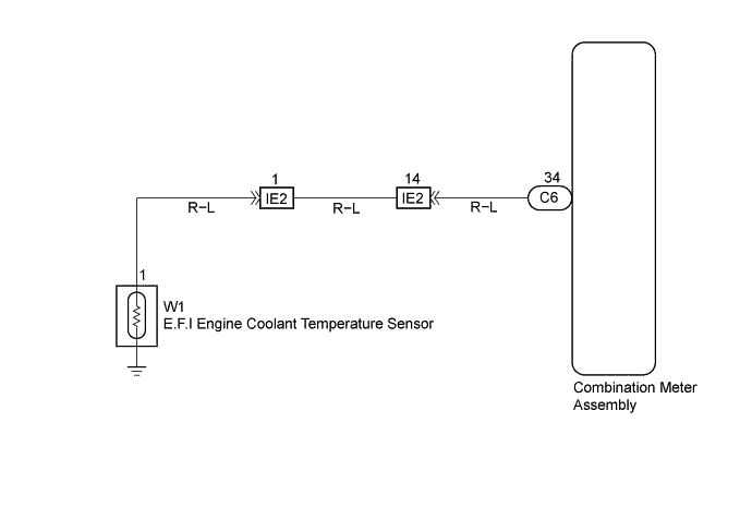
WIRING DIAGRAM
INSPECTION PROCEDURE
PROCEDURE
-
INSPECT COMBINATION METER ASSEMBLY
-
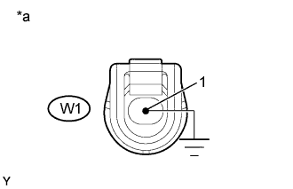
Text in Illustration *a E.F.I. Engine Coolant Temperature Sensor Connector Front view: (Wire Harness Side) Disconnect the connector with E.F.I. engine coolant temperature sensor.
-
Check the meter needle conditions according to the table below.
Standard Wire Connection Condition Specified Condition 1 to Body ground Short circuit
(Ignition Switch ON)
The needle indicates above "H" All the line are disconnected Open circuit
(Ignition Switch ON)
The needle indicates below "C"
NG 
CHECK HARNESS AND CONNECTOR (BETWEEN E.F.I ENGINE COOLANT TEMPERATURE SENSOR AND COMBINATION METER ASSEMBLY) Click here
OK 
REPLACE E.F.I. ENGINE COOLANT TEMPERATURE SENSOR
-
-
CHECK HARNESS AND CONNECTOR (BETWEEN E.F.I ENGINE COOLANT TEMPERATURE SENSOR AND COMBINATION METER ASSEMBLY)
-
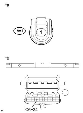
Text in Illustration *a E.F.I Engine Coolant Temperature Sensor Connector Front View: *b Combination Meter Assembly Wier Harness View: Disconnect the C6 and W1 connectors.
-
Measure the resistance according to the value(s) in the table below.
Standard Tester connection Condition Specified condition C6-34 - W1-1 Always Below 1 Ω C6-34 - Body ground Always 10 kΩ or higher
NG 
REPAIR OR REPLACE HARNESS OR CONNECTOR
OK 
-
-
CHECK CHECK THAT MALFUNCTION DISAPPEARS A KNOWN GOOD COMBINATION METER IS INSTALLED
Standard Malfunction disappears.
NG
REPLACE E.F.I. ENGINE COOLANT TEMPERATURE SENSOR
OK
REPLACE COMBINATION METER ASSEMBLY