METER / GAUGE SYSTEM (for General Countries) Fuel Receiver Gauge Malfunction
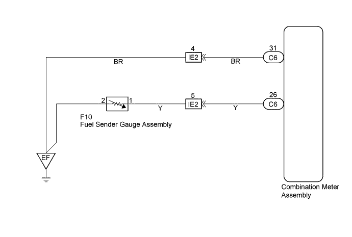
WIRING DIAGRAM
INSPECTION PROCEDURE
PROCEDURE
-
INSPECT HARNESS OR CONNECTOR
-
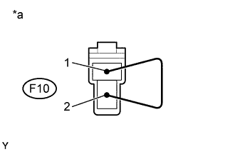
Text in Illustration *a Fuel Sender Gauge Connector Front View: (Wire Harness Side) Disconnect the connector from fuel sender gauge assembly.
-
Check the meter indicator conditions according to the table below.
Standard Wire Connection Condition Specified Condition 1 to 2 Short circuit
(Ignition Switch ON)
Fuel gauge indicates "F" or more (Combination meter) -
Measure the voltage accoding to the value(s) in the table below.
Standard Tester Connection Condition Specified Condition 1 - Body ground Ignition switch ON 4 to 7 V
NG 
CHECK HARNESS AND CONNECTOR (BETWEEN FUEL SENDER GAUGE ASSEMBLY AND COMBINATION METER ASSEMBLY) Click here
OK 
-
-
INSPECT FUEL SENDER GAUGE ASSEMBLY
-
Remove the fuel sender gauge assembly.
-
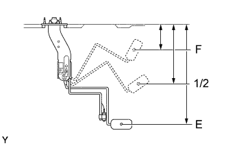
Check that the float position is between E and F and measure resistance between the terminals 1 and 2 of connector.
-
Measure the resistance according to the value(s) in the table below.
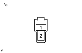
Standard Float level Float position mm (in.) Resistance (Ω) F 71.7 (2.82) to 79.7 (3.14) 2.4 to 3.6 1/2 173.3 (6.82) 28 to 31 E 284.7 (11.21) to 292.7 (11.53) 107.5 to 112.5 Text in Illustration *a Connector Front View:
NG 
REPLACE FUEL SENDER GAGE ASSEMBLY
OK 
REPLACE COMBINATION METER ASSEMBLY
-
-
CHECK HARNESS AND CONNECTOR (BETWEEN FUEL SENDER GAUGE ASSEMBLY AND COMBINATION METER ASSEMBLY)
-
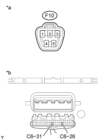
Text in Illustration *a Fuel Sender Gauge Assembly Connector Front View: *b Combination Meter Assembly Wire Harness View: Disconnect the C6 and F10 connectors.
-
Measure the resistance according to the value(s) in the table below.
Standard Tester connection Condition Specified condition C6-26 - F10-1 Always Below 1 Ω C6-31 - Body ground Always Below 1 Ω F10-2 - Body ground Always Below 1 Ω C6-26 - Body ground Always 10 kΩ or higher
NG
REPAIR OR REPLACE HARNESS OR CONNECTOR
OK
REPLACE COMBINATION METER ASSEMBLY
-