METER / GAUGE SYSTEM (for General Countries) Speedometer Malfunction
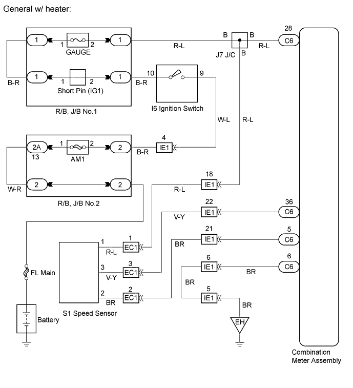
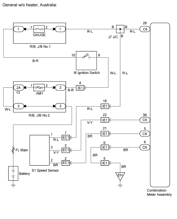
WIRING DIAGRAM
INSPECTION PROCEDURE
PROCEDURE
-
INSPECT COMBINATION METER ASSEMBLY
INSPECTION USING OSCILLOSCOPE
-
Check the input signal waveform.
-
Remove the combination meter assembly with the connectors still connected.
-
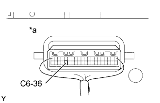
Connect the oscilloscope to the terminals C6-36 and body ground.
-
Start the engine.
-
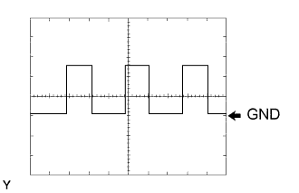
Check the signal waveform according to the condition(s) in the table below.
Item Condition Tool setting 5 V/DIV, 20 ms/DIV Vehicle condition Driving at approx. 20 km/h
OK As shown in the illustration Tech Tips
As the vehicle speed increases, the cycle of the signal waveform narrows.
Text in Illustration *a Wire Harness View: -
NG 
INSPECT COMBINATION METER ASSEMBLY Click here
OK 
REPLACE COMBINATION METER ASSEMBLY
-
-
INSPECT COMBINATION METER ASSEMBLY
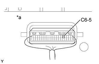
Text in Illustration *a Wire Harness View:
-
Measure the resistance according to the value(s) in the table below.
Standard Tester connection Condition Specified condition C6-5 - Body ground Always Below 1 Ω
NG 
REPLACE COMBINATION METER ASSEMBLY
OK 
-
-
CHECK HARNESS AND CONNECTOR (BETWEEN SPEED SENSOR AND COMBINATION METER ASSEMBLY)
-
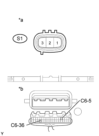
Disconnect the C6 and S1 connectors.
-
Measure the resistance according to the value(s) in the table below.
Standard Tester connection Specified condition C6-36 - S1-3 Below 1 Ω C6-5 - S1-2 Below 1 Ω C6-36 - Body ground 10 kΩ or higher -
Measure the voltage according to the value(s) in the table below.
Standard Tester connection Condition Specified condition S1-1 - Body ground Ignition switch OFF → ON Below 1V → 10 to 14V
NG
REPAIR OR REPLACE HARNESS OR CONNECTOR
OK
REPLACE SPEED SENSOR
-