METER / GAUGE SYSTEM (for General Countries) Tachometer Malfunction
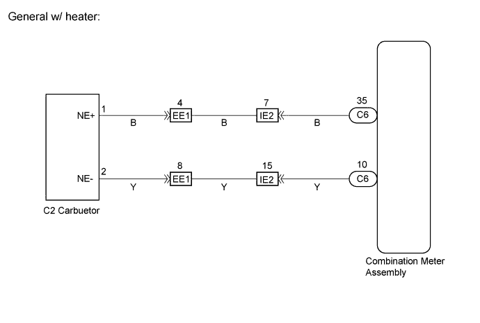
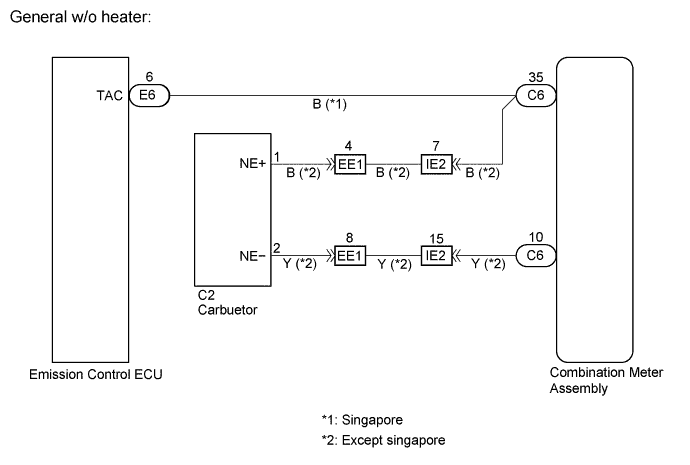
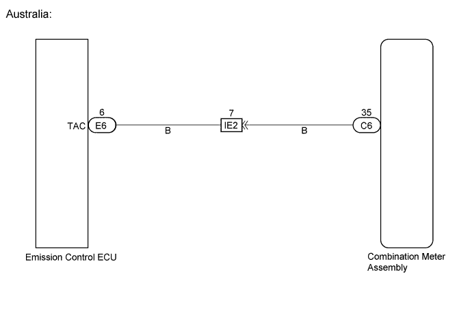
WIRING DIAGRAM
INSPECTION PROCEDURE
PROCEDURE
-
DESTINATION CHECK
-
Check destination and spec according to the table below.
A General w/ heater, General w/o heater (Except sigapore) B General w/o heater (Sigapore), Australia
B 
INSPECT COMBINATION METER ASSEMBLY Click here
A 
-
-
INSPECT COMBINATION METER ASSEMBLY
INSPECTION USING OSCILLOSCOPE
-
Check the input signal waveform
-
Remove the combination meter assembly with the connectors still connected.
-
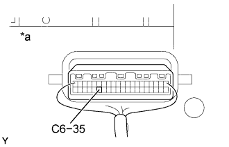
Connect the oscilloscope to the terminals C6-35 and body ground.
-
Start the engine.
-
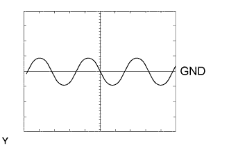
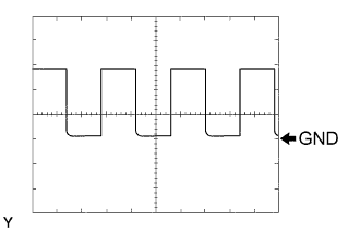
Check the signal waveform according to the condition( s) in the table below.
Item Condition Tool setting 1 V/DIV, 10 ms/DIV Vehicle condition Engine idle speed OK As shown in the illustration Tech Tips
As the vehicle speed increases, the cycle of the signal waveform narrows.
Text in Illustration *a Wire Harness View:
-
NG
INSPECT REVOLUTION DETECTOR ASSEMBLY Click here
OK 
REPLACE COMBINATION METER ASSEMBLY
-
-
INSPECT REVOLUTION DETECTOR ASSEMBLY
-
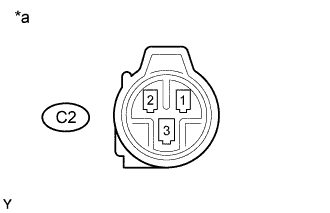
Text in Illustration *a Connector Front View: Remove the revolution detector assembly.
-
Measure the resistance according to the value(s) in the table below.
Standard Tester connection Condition Specified condition 1 - 2 Always Approx. 730 Ω
NG 
REPLACE REVOLUTION DETECTOR ASSEMBLY
OK
-
-
CHECK HARNESS AND CONNECTOR (BETWEEN COMBINATION METER ASSEMBLY AND REVOLUTION DETECTOR ASSEMBLY)
-
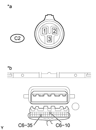
Text in Illustration *a Revolution Detector assembly Wier Harness View: *b Combination Meter assembly Wier Harness View: Disconnect the C2 and C6 connectors.
-
Measure the resistance according to the value(s) in the table below.
Standard Tester connection Condition Specified condition C6-35 - C2-1 Always Below 1 Ω C6-10 - C2-2 Always Below 1 Ω C6-35 - Body ground Always 10kΩ or higher C6-10 - Body ground Always 10kΩ or higher
NG
REPAIR OR REPLACE HARNESS OR CONNECTOR
OK
REPLACE COMBINATION METER ASSEMBLY
-
-
INSPECT COMBINATION METER ASSEMBLY
INSPECTION USING OSCILLOSCOPE
-
Check the input signal waveform.
-
Remove the combination meter assembly with the connectors still connected.
-
Connect the oscilloscope to the terminals C6-35 and body ground.
-
Start the engine.
-
Check the signal waveform according to the condition(s) in the table below.
Item Condition Tool setting 1 V/DIV, 10 ms/DIV Vehicle condition Engine idle speed OK As shown in the illustration Tech Tips
As the vehicle speed increases, the cycle of the signal waveform narrows.
Text in Illustration *a Wire Harness View:
-
NG
CHECK HARNESS AND CONNECTOR (BETWEEN EMISSION CONTROL ECU AND COMBINATION METER ASSEMBLY) Click here
OK
REPLACE COMBINATION METER ASSEMBLY
-
-
CHECK HARNESS AND CONNECTOR (BETWEEN EMISSION CONTROL ECU AND COMBINATION METER ASSEMBLY)
-
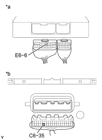
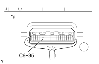
Text in Illustration *a Emission Control ECU Wier Harness View: *b Combination Meter Assembly Wier Harness View: Disconnect the C6 and E6 connectors.
-
Measure the resistance according to the value(s) in the table below.
Standard Tester connection Condition Specified condition C6-35 - E6-6 Always Below 1 Ω C6-35 - Body ground Always 10kΩ or higher
NG
REPAIR OR REPLACE HARNESS OR CONNECTOR
OK
REPLACE EMISSION CONTROL ECU
-