METER / GAUGE SYSTEM (for General Countries) Entire Combination Meter does not Operate
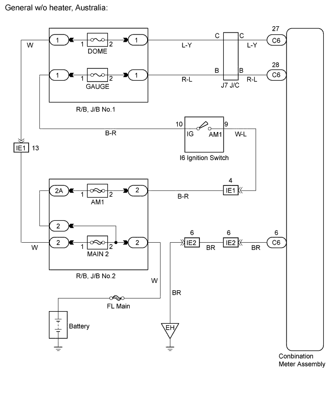
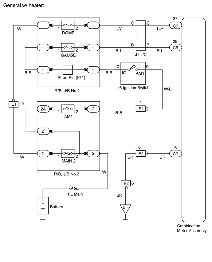
WIRING DIAGRAM
INSPECTION PROCEDURE
PROCEDURE
-
INSPECT COMBINATION METER ASSEMBLY
-
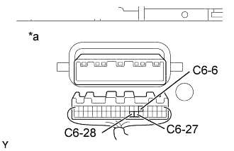
Text in Illustration *a Wire Harness View: Measure the resistance according to the value(s) in the table below.
Standard Terminal No Condition Specified condition C6-6 - Body ground Always Below 1 Ω -
Measure the voltage according to the value(s) in the table below.
Standard Terminal No Condition Specified condition C6-27 - Body ground Always 10 to 14 V C6-28 - Body ground Ignition switch ON 10 to 14 V
NG 
REPAIR OR REPLACE HARNESS OR CONNECTOR
OK 
REPLACE COMBINATION METER ASSEMBLY
-