METER / GAUGE SYSTEM (for General Countries) TERMINALS OF ECU

-
COMBINATION METER ASSEMBLY
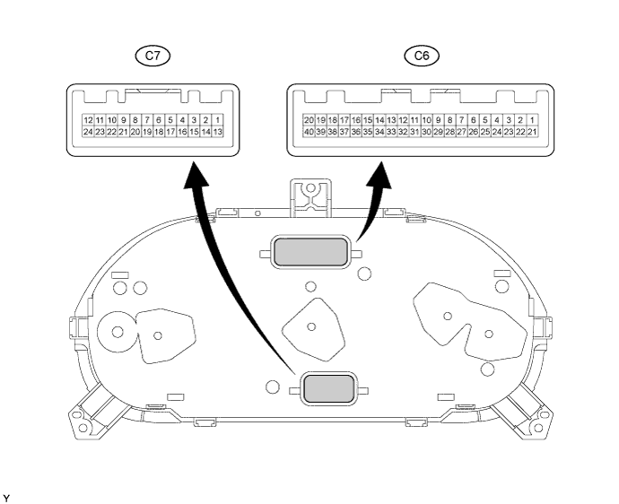
Terminal No. Wire harness side C6 2 Headlight LH/RH 3 Emission Control ECU 5 Speed Sensor 14 Low Oil Pressure Warning Switch 16 Parking Brake Switch 17 Turn Signal Flasher Relay 24 Turn Signal Flasher Relay 25 GND 26 Fuel Sender Gauge 27 DOME Fuse 28 GAUGE Fuse 29 TAIL Fuse 30 GND 31 GND 34 E.F.I Engine Coolant Temperature Sensor 35 Emission Control ECU 36 Speed Sensor 37 4P-OUT 38 4P-OUT 39 Low Oil Level Warning Switch C7 7 Alternator 8 GAUGE Fuse 10 GND 12 Fuel Filter 
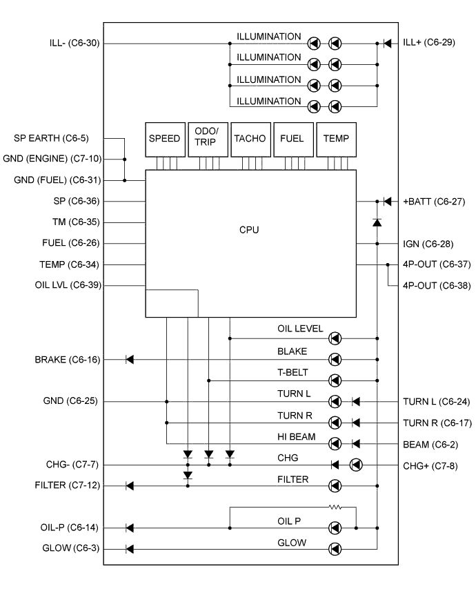
Symbols (Terminals No.) Wiring Color Terminal Description Condition Specified Condition BEAM (C9-2) - Body ground R-G - Body ground Hi-Beam signal Headlight dimmer switch Lo → Hi 10 to 14 V → Below 1 V GLOW (C6-3) - Body ground G-W Body ground GLOW signal GLOW indicator ON → OFF Below 1 V → 10 to 14 V SP EARTH (C6-5) - Body ground BR - Body ground Ground (Speed sensor) Always Below 1 Ω OIL-P (C6-14) - Body ground P-L - Body ground OIL pressure signal OIL/P warning light ON → OFF Below 1 V → 10 to 14 V BRAKE (C6-16) - Body ground B-Y - Body ground Brake signal Ignition switch ON, BRAKE warning light ON → OFF Below 1 V → 10 to 14 V TURN R (C6-17) - Body ground G-Y - Body ground Turn signal R Ignition switch ON, turn signal RH indicator OFF → ON Below 1 V → 10 to 14 V TURN L (C6-24) - Body ground G-B - Body ground Turn signal L Ignition switch ON, turn signal LH indicator OFF → ON Below 1 V → 10 to 14 V GND (C6-25) - Body ground W-B - Body ground Ground Always Below 1 Ω FUEL (C6-26) - Body ground Y - Body ground Fuel signal Ignition switch ON, fuel level is FULL → EMPTY Below 1 V → 4 to 7 V +BATT (C6-27) - Body ground L-Y - Body ground Battery Always 10 to 14 V IGN (C6-28) - Body ground R-L - Body ground Ignition switch signal Ignition switch OFF → ON Below 1 V → 10 to 14 V ILL+ (C6-29) - Body ground G - Body ground Illumination signal Tail light OFF → ON Below 1 V → 10 to 14 V ILL- (C6-30) - Body ground W-B - Body ground Ground Always Below 1 Ω GND (FUEL) (C6-31) - Body ground BR - Body ground Ground (FUEL) Always Below 1 Ω TEMP (C6-34) - Body ground R-L - Body ground Water temperature signal Ignition switch ON, Coolant temperature is 90°C (194°F) Below 1 V → 10 to 14 V TM (C6-35) - Body ground B - Body ground Tacho meter signal (Input) Engine running Puls generation
(See waveform 1)
SP (C6-36) - Body ground V-Y - Body ground Speed signal (Input) Ignition switch ON and turn the wheel slowly Puls generation
(See waveform 2)
4P-OUT (C6-37) - Body ground V-W - Body ground Speed signal (Output) Ignition switch ON and turn the wheel slowly Puls generation
(See waveform 2)
OIL LVL (C6-39) - Body ground B-R - Body ground Engine oil level signal Ignition switch ON, engine oil level warning light ON → OFF Below 1 V → 10 to 14 V CHG- (C7-7) - Body ground Y - Body ground Charge signal Engine running → Stopped Below 1 V → 10 to 14 V CHG+ (C7-8) - Body ground R-L - Body ground Charge signal Ignition switch OFF → ON Below 1 V → 10 to 14 V GND (ENGINE) (C7-10) - Body ground BR - Body ground Ground (Engine) Always Below 1 Ω FILTER (C7-12) - Body ground W - Body ground Fuel filter signal Fuel filter indicator ON → OFF Below 1 V → 10 to 14 V
-
Waveform 1
Waveform 1 (Reference): Item Contents Tool setting 5 V/DIV, 10 ms/DIV Vehicle condition Engine idle speed -
Waveform 2
Waveform 2 (Reference): Item Contents Tool setting 5 V/DIV, 20 ms/DIV Vehicle condition Driving at approx. 20 km/h (12 mph) Tech Tips
As vehicle speed increases, the cycle of the signal waveform narrows.
-