METER / GAUGE SYSTEM (except General Countries) Engine Coolant Temperature Receiver Gauge Malfunction
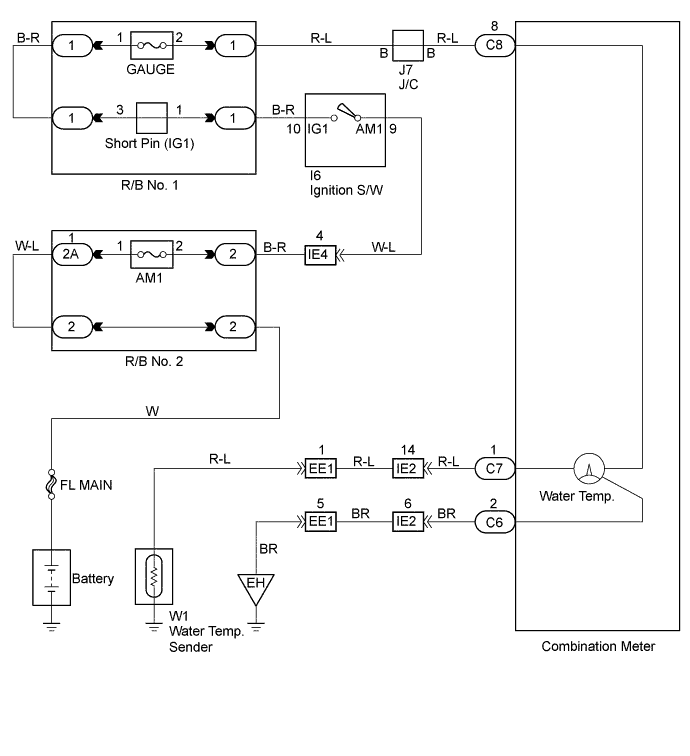
WIRING DIAGRAM
INSPECTION PROCEDURE
PROCEDURE
-
INSPECT WATER TEMPERATURE SENDER GAUGE ASSEMBLY
-
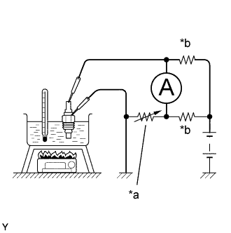
Text in Illustration *a Slide Rheostat *b 35.53 to 35.73 Ω Remove the water temperature sender gauge assembly.
-
Check resistance.
-
Connect the battery , ammeter, slide rheostat and wire harness, as shown in the illustration.
-
Adjust the ammeter pointer to indicate "0" using the slide rheostat, then read the rheostat indication.
Standard Temperature °C (°F) Resistance (Ω) 50 (122.0) 160 - 240 120 (248.0) 17.1 - 21.2
-
NG 
REPLACE WATER TEMPERATURE SENDER GAUGE ASSEMBLY
OK 
-
-
CHECK HARNESS AND CONNECTOR
-
Check open or short of wire harness between combination meter and water temperature sender gauge assembly.
NG
REPAIR OR REPLACE HARNESS OR CONNECTOR
OK
-
-
INSPECT FUEL RECEIVER GAUGE SUB-ASSEMBLY (WATER TEMPERATURE RECEIVER GAUGE)
-
Remove the combination meter assembly.
-
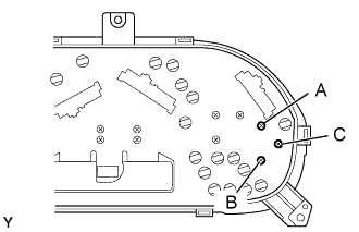
Check resistance of water temperature receiver gauge.
-
Measure resistance between terminals of the fuel receiver gauge sub-assembly, as shown in the chart.
Standard: resistance Tester connection Standard resistance (Ω) A - B Approx. 187 Ω A - C Approx. 247 Ω B - C Approx. 90 Ω
-
NG
REPLACE FUEL RECEIVER GAUGE SUB-ASSEMBLY
OK 
REPLACE METER CIRCUIT PLATE
-