METER / GAUGE SYSTEM (except General Countries) Tachometer Malfunction
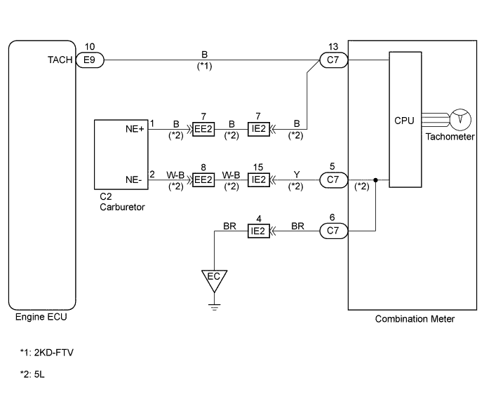
WIRING DIAGRAM
INSPECTION PROCEDURE
PROCEDURE
-
CHECK ENGINE SERIAL NUMBER
-
Confirm engine models.
A B 5L (Singapore) and 2KD-FTV 5L (Except Singapore)
B 
INSPECT COMBINATION METER ASSEMBLY Click here
A 
-
-
INSPECT COMBINATION METER ASSEMBLY
-
Remove the combination meter assembly with connectors still connected.
-
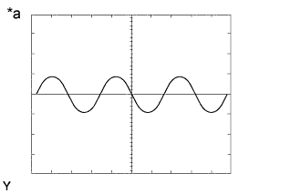
Check the signal waveform.
-
Start engine.
-
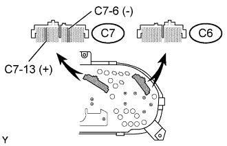
Connect the oscilloscope to the terminal C7-13 and C7-6 of combination meter assembly.
-
Check the signal waveform.
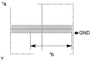

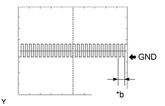
Text in Illustration *a 5L Engine *b 18.5 Pulse/Rev. *c 2KD-FTV Engine *d 2 Pulse/Rev. Result: A OK B NG (2KD-FTV) C NG (5L Singapore)
-
B
INSPECT ECM Click here
C
INSPECT EMISSION CONTROL ECU Click here
A
-
-
INSPECT ENGINE TACHOMETER ASSEMBLY
-
Remove the combination meter assembly.
-
Check resistance of engine tachometer assembly.
-
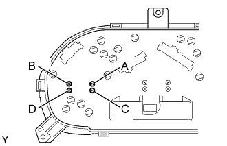
Measure resistance between terminals of the engine tachometer assembly, as shown in the chart.
Standard: resistance Tester connection Standard resistance (Ω) A - D Approx. 160 Ω B - C Approx. 160 Ω
-
NG 
REPLACE ENGINE TACHOMETER ASSEMBLY
OK
-
-
INSPECT TOTAL COUNTER MODULE ECU
-
Check malfunction disappear when a known good total counter module ECU is installed.
A B Malfunction does not disappear Malfunction disappear
B
REPLACE TOTAL COUNTER MODULE ECU
A 
REPLACE METER CIRCUIT PLATE
-
-
INSPECT ECM
-
Remove the ECM with connectors still connected.
-
Check the signal waveform.
-
Start engine.
-
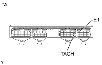
Connect the oscilloscope to the terminal TACH and E1 of ECM.
-
Check the signal waveform.
Text in Illustration *a ECM terminals *b 2 Pulse/Rev.
-
NG
CHECK AND REPLACE ECM
OK
REPAIR OR REPLACE HARNESS OR CONNECTOR
-
-
INSPECT EMISSION CONTROL ECU
-

Remove the emission control ECU with connectors still connected.
-
Check the signal waveform.
-
Start engine.
-
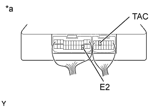
Connect the oscilloscope to the terminal TAC and E1 of emission control ECU.
-
Check the signal waveform.
Text in Illustration *a Emission control ECU terminals *b 5L Engine *c 18.5 Pulse/Rev.
-
NG
REPLACE EMISSION CONTROL ECU
OK
REPAIR OR REPLACE HARNESS OR CONNECTOR
-
-
INSPECT COMBINATION METER ASSEMBLY
-
Remove the combination meter assembly with connectors still connected.
-
Check the signal waveform.
-
Start engine
-
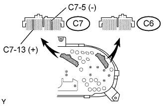
Connect the oscilloscope to the terminal C7-13 and C7-5 of combination meter assembly.
-
Check the signal waveform.
Text in Illustration *a 18.5 Pulse/Rev.
-
OK
INSPECT ENGINE TACHOMETER ASSEMBLY Click here
NG
-
-
INSPECT REVOLUTION DETECTOR ASSEMBLY
-
Remove the revolution detector assembly.
-
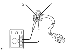
Check resistance.
-
Measure resistance between terminals 1 and 2 of revolution detector assembly.
Standard 730 Ω
-
NG
CHECK AND REPLACE DETECTOR ASSEMBLY, REVOLUTION
OK
REPAIR OR REPLACE HARNESS OR CONNECTOR
-
-
INSPECT ENGINE TACHOMETER ASSEMBLY
-
Remove the combination meter assembly.
-
Check resistance of engine tachometer assembly.
-
Measure resistance between terminals of the engine tachometer assembly, as shown in the chart.
Standard: resistance Tester connection Standard resistance (Ω) A - D Approx. 160 Ω B - C Approx. 160 Ω
-
NG
REPLACE ENGINE TACHOMETER ASSEMBLY
OK
-
-
INSPECT TOTAL COUNTER MODULE ECU
-
Check malfunction disappear when a known good total counter module ECU is installed.
A B Malfunction does not disappear Malfunction disappear
B
REPLACE TOTAL COUNTER MODULE ECU
A
REPLACE METER CIRCUIT PLATE
-